• The move to the new server is done. There are some software and database maintenance updates in process. This has us passing the hat around to help out. We appreciate any donations. Seriously, even a dollar helps. The payment page may be found here - https://www.audiokarma.org/support.html

G6000 Resistor type

Yemm66

Active Member
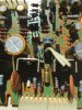
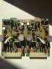
Hello. Need some help identifying this resistor please. Not sure what to order to replace it. It's on F-2856 board. Photos of burnt resistor (R41) position and the opposite side with the still good and working resistor. I usually order form Digikey, buy any link would be gratefully appreciated. Thanks for the help! J.
 

Attachments

  • IMG_2090.JPG
    IMG_2090.JPG
    34.4 KB · Views: 26
  • IMG_2091.JPG
    IMG_2091.JPG
    35.9 KB · Views: 26
  • IMG_2092.JPG
    IMG_2092.JPG
    34.6 KB · Views: 28
  • IMG_2095.JPG
    IMG_2095.JPG
    72.3 KB · Views: 30
  • IMG_2096.JPG
    IMG_2096.JPG
    61.2 KB · Views: 28
  • IMG_2097.JPG
    IMG_2097.JPG
    73.4 KB · Views: 31
Register to hide this ad
Also, I could not get the left side to bias. The manual says 4.5mv and I could not get it past 2mv. Do I need a new trim pot? Would that help fix that issue?
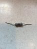
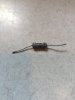
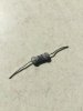
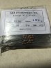
I also found some resistors in my stash. Here is a photo of them. Would this substitute for the resistor I have that is burned? They are quite a bit smaller compared to the one on the board. Thanks again!
 

Attachments

  • IMG_2093.JPG
    IMG_2093.JPG
    45.7 KB · Views: 10
  • IMG_2094.JPG
    IMG_2094.JPG
    45.5 KB · Views: 10
Also, I could not get the left side to bias. The manual says 4.5mv and I could not get it past 2mv. Do I need a new trim pot? Would that help fix that issue?
I also found some resistors in my stash. Here is a photo of them. Would this substitute for the resistor I have that is burned? They are quite a bit smaller compared to the one on the board. Thanks again!
No, those are Carbon Composite resistors, not suitable.
Sansui use those type of resistors as protection in their circuits. You can use a 1watt Metal Film.
The issue with the bias may not be the trimmer.
If R41 has burned up, the bias has run away. So you will need to test the surrounding transistors and the STV3 thermal tracking diode.
Also R33 and R43 are suspect, and if they have been subject to overcurrent, they will also have gone hiZ.
So theres a bit to do.
Have a look at those things and let us know how you get on..
 
No, those are Carbon Composite resistors, not suitable.
Sansui use those type of resistors as protection in their circuits. You can use a 1watt Metal Film.
The issue with the bias may not be the trimmer.
If R41 has burned up, the bias has run away. So you will need to test the surrounding transistors and the STV3 thermal tracking diode.
Also R33 and R43 are suspect, and if they have been subject to overcurrent, they will also have gone hiZ.
So theres a bit to do.
Have a look at those things and let us know how you get on..
Hi and thanks for the information. I am rather new to trouble shooting any of these things. I have a multimeter. Do I set it to DC V? Where is the STV3 located on the board? How do I set the multimeter across it to test? Where do I put the probes? Same for the transistors? Also, are the R41 a 10 ohm resistor? I have half a service manual that looks like it may be a 100 ohm. Not sure. Thanks again!
 
I have a multimeter. Do I set it to DC V?
When you're measuring DC voltage - you do. Practically everything but line voltage, incandescent illumination circuits and signal paths are DC. Nevertheless, you're gonna have to learn how to measure current in series pretty soon if you want to debug any of it and be able to recognize where AC is.
Where is the STV3 located on the board?
It's not. On this board it's STV-4H. and it's the diodes that piggy back the TR-13/TR-14 power transistors heat sinks.
How do I set the multimeter across it to test?
You pull at least one leg out of circuit and use the DMM diode test to read forward voltage. You'll need to distinguish anode from cathode for this. You're also going to need to identify simple rectifier diodes, Zener diodes, temp/co diodes and other vintage beasts like the red dotted VD1212's and older Germanium diodes.
Same for the transistors?
No. Transistors are bi-polar junctions, like 2 diodes hooked together in a special configuration and they have 3 'legs'. You're gonna have to look it up, identify the collector, base and emitter and learn how to test PNP and NPN transistors using a DMM, or purchase a simple component tester. For most intents and purposes, you're going to have to pull them out of circuit as well.
Also, are the R41 a 10 ohm resistor?
It sure looks like it, unless the first band is red instead of brown or one of the black bands is something else.
I have half a service manual that looks like it may be a 100 ohm
The other half is downloadable for free and it says it's a 10Ω resistor. The 4 band color code also seems to agree with the 10Ω value and you're gonna have to learn about it too. When you're done, enter the domain of capacitors.
I am rather new to trouble shooting any of these things.
You sure picked the wrong unit to start learning. These are the pinnacle of electronics of 70's home amplification equipment and you landed smack on the driver amp. Not a good choice! Perhaps start with simpler projects or invite a knowledgeable pal for a basic 101. Look up a simple tool named a 'dim bulb tester' (DBT) which is a basic current limiting gizmo, and build your self one for peanuts. It's easy and it's practically a life saver and would sure help you not frying your unit by accident.
Thanks again!
You're welcome!
 
When you're measuring DC voltage - you do. Practically everything but line voltage, incandescent illumination circuits and signal paths are DC. Nevertheless, you're gonna have to learn how to measure current in series pretty soon if you want to debug any of it and be able to recognize where AC is.
It's not. On this board it's STV-4H. and it's the diodes that piggy back the TR-13/TR-14 power transistors heat sinks.
You pull at least one leg out of circuit and use the DMM diode test to read forward voltage. You'll need to distinguish anode from cathode for this. You're also going to need to identify simple rectifier diodes, Zener diodes, temp/co diodes and other vintage beasts like the red dotted VD1212's and older Germanium diodes.
No. Transistors are bi-polar junctions, like 2 diodes hooked together in a special configuration and they have 3 'legs'. You're gonna have to look it up, identify the collector, base and emitter and learn how to test PNP and NPN transistors using a DMM, or purchase a simple component tester. For most intents and purposes, you're going to have to pull them out of circuit as well.
It sure looks like it, unless the first band is red instead of brown or one of the black bands is something else.
The other half is downloadable for free and it says it's a 10Ω resistor. The 4 band color code also seems to agree with the 10Ω value and you're gonna have to learn about it too. When you're done, enter the domain of capacitors.
You sure picked the wrong unit to start learning. These are the pinnacle of electronics of 70's home amplification equipment and you landed smack on the driver amp. Not a good choice! Perhaps start with simpler projects or invite a knowledgeable pal for a basic 101. Look up a simple tool named a 'dim bulb tester' (DBT) which is a basic current limiting gizmo, and build your self one for peanuts. It's easy and it's practically a life saver and would sure help you not frying your unit by accident.
You're welcome!

Thank you Tom. I appreciate your help. I will do some reading.
 
Back
Top Bottom