Smelta&styr
New Member
Hi all, hoping someone who knows these tables can point me in a direction. I'm fairly new to this kind of troubleshooting, so apologies if I'm missing something obvious.
The symptom: Touch either speed button and the motor starts, but it drops back to stop as soon as I lift my finger. Sometimes it runs for a few seconds or even a couple of minutes first, then stops on its own. It isn't consistent. It also seems to alternate between the two speed buttons, so some evenings 45 holds and 33 doesn't, other times the reverse. All bulbs light up. The table worked fine until recently and I didn't change anything in between.
What I've measured (DC, against chassis):
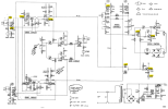
Unregulated side after the rectifier sits steady at 16V. The manual says 14V, and my table is on the 220V tap with 230V mains, so I assume that explains some of it?
Across the zener I get 7.76V, which looks about right.
The regulated rail was originally wandering between 9.5V and 12.3V on its own in stop. After I replaced the 470µF filter cap it became much steadier, now sitting at 10.4V and dipping evenly to 9.8V while a speed button is held. But it's still 1.4V above where it should be, and the trimmer the manual says to use for setting it is a fixed resistor on my board, so there's nothing to adjust.
The thing I noticed last night: while holding a speed button, the bulb under the button and the bulb lighting the LDR both pulse in brightness, and they pulse together, in sync. Does that confirm it's the supply rather than anything in the switching logic? That's how I've been reading it, but I'd rather hear from someone who knows.
Other things I've tried: cleaned the touch pads with IPA and let them dry, checked the ground trace around the board edge is continuous, reflowed some joints including one that looked scorched near the stop circuit, and tried adjusting the auto stop sensitivity trimmer.
My questions: Is 1.4V high on the rail enough on its own to stop the flip flop latching? If the supply is the problem and the filter cap didn't fix it, am I right that the pass transistor and its driver are what's left? Or should I be looking somewhere else entirely? And is there a sensible way to check those transistors in circuit?
Thanks for any pointers.
The symptom: Touch either speed button and the motor starts, but it drops back to stop as soon as I lift my finger. Sometimes it runs for a few seconds or even a couple of minutes first, then stops on its own. It isn't consistent. It also seems to alternate between the two speed buttons, so some evenings 45 holds and 33 doesn't, other times the reverse. All bulbs light up. The table worked fine until recently and I didn't change anything in between.
What I've measured (DC, against chassis):
Unregulated side after the rectifier sits steady at 16V. The manual says 14V, and my table is on the 220V tap with 230V mains, so I assume that explains some of it?
Across the zener I get 7.76V, which looks about right.
The regulated rail was originally wandering between 9.5V and 12.3V on its own in stop. After I replaced the 470µF filter cap it became much steadier, now sitting at 10.4V and dipping evenly to 9.8V while a speed button is held. But it's still 1.4V above where it should be, and the trimmer the manual says to use for setting it is a fixed resistor on my board, so there's nothing to adjust.
The thing I noticed last night: while holding a speed button, the bulb under the button and the bulb lighting the LDR both pulse in brightness, and they pulse together, in sync. Does that confirm it's the supply rather than anything in the switching logic? That's how I've been reading it, but I'd rather hear from someone who knows.
Other things I've tried: cleaned the touch pads with IPA and let them dry, checked the ground trace around the board edge is continuous, reflowed some joints including one that looked scorched near the stop circuit, and tried adjusting the auto stop sensitivity trimmer.
My questions: Is 1.4V high on the rail enough on its own to stop the flip flop latching? If the supply is the problem and the filter cap didn't fix it, am I right that the pass transistor and its driver are what's left? Or should I be looking somewhere else entirely? And is there a sensible way to check those transistors in circuit?
Thanks for any pointers.