• The move to the new server is done. There are some software and database maintenance updates in process. This has us passing the hat around to help out. We appreciate any donations. Seriously, even a dollar helps. The payment page may be found here - https://www.audiokarma.org/support.html

GloTone Cockeyed Monkey - A Directly Coupled SET

A choke load with an inductance value so high that impedance at all relevant frequencies is effectively infinite, akin to a CCS. My understanding is that, like an OPT, it can swing above B+. And also like an OPT, it can introduce nonlinearities. Really useful for getting big voltage swings out of a driver tube without running the extra b+ necessary for a CCS.

Also, wow, I hadn't really looked at the schematic. Running a choke load in between an elevated cathode and the plate of the driver tube is such an interesting way to do direct coupling.
 
Last edited:
@FlaCharlie Have you measured the output tube current flow? I'm really curious how tightly controlled it is, although luckily doesn't make a huge difference with SE designs, but it seems to me that proper bias for the output stage is contingent on all the component values (including the DCR of the choke) being relatively on target. Future builders shouldn't go about replicating this amp with different plate chokes unless they recalculate the relationship between the choke and the two voltage divider resistors in the output stage cathode circuit.
 
Still the same question, how does that work?
In order to develop a voltage at the grid of the output tube, the driver needs to work into a load. Typically that would be a resistor but in this case a choke provides a load but also allows voltage swing above the plate voltage and greater drive power for a given anode voltage.
 
It also just occurred to me that this setup kind of approximates fixed bias, because the voltage swings on the cathode load are applied to both the cathode and the grid, with an offset (the bias voltage) provided by the constant current draw through the plate choke.

I'm curious what tube gurus think about the possibility of bypassing the 1.8k resistor with a capacitor so that you're not wasting a bunch of signal output on driving that resistor?
 
The cathode is already bypassed, but to B+ instead of ground using that 50uf cap. B+ is AC ground anyway so it really makes no difference.
 
I am sort of curious about the tie to b+ instead of ground though. I don't know if there was any specific reason or advantage to that vs to ground.
 
I was thinking maybe applying the B+ ripple to the cathode so that it cancels out to an extent? And it also gets applied to the grid, so you don't have to worry about that aspect.
 
Oh like a hum bucking thing ? Maybe

Aa5 types and other cheapie se circuits with poor filtering did this with screen taps
 
@FlaCharlie Have you measured the output tube current flow? I'm really curious how tightly controlled it is, although luckily doesn't make a huge difference with SE designs, but it seems to me that proper bias for the output stage is contingent on all the component values (including the DCR of the choke) being relatively on target. Future builders shouldn't go about replicating this amp with different plate chokes unless they recalculate the relationship between the choke and the two voltage divider resistors in the output stage cathode circuit.
The current was calculated at idle, not dynamically, if that's what you're asking. It's posted on the schematic. As I understand it, current is essentially constant in a SE amp which is Class A by definition.

The DCR of the Hammond 156c plate chokes shown on the schematic are the measured values I got, which are actually lower than Hammond's published specs. Their biggest limitation is the maximum current rating of 8mA. Plate chokes that can handle higher current seem to be considerably more expensive.

As I said, I'm not very technically oriented. Lots of technical details and discussion can be found by searching for DRD amplifier and variations like Direct Reactance Drive / Monkey / Free Lunch. The basic design was developed by Jack Elliano of Electraprint. Ron Wellbourne then sold them as kits. The 50uf caps are known as Ultrapath caps and that aspect is also discussed in detail if you search.
 
What I'm asking is how closely the actual idle current matches the calculated idle current on the schematic. Was just curious.
 
What I'm asking is how closely the actual idle current matches the calculated idle current on the schematic. Was just curious.
It seems like the voltages on the schematic are actual measured voltages, and then the currents are calculated from that. So that can be taken as actual idle currents if we accept Ohm's law.
 
It seems like the voltages on the schematic are actual measured voltages, and then the currents are calculated from that. So that can be taken as actual idle currents if we accept Ohm's law.
That's correct. All voltages are measured, not based on a sim like Spice, which I have no idea how to use. I did run a PSUD sim but the results are suspect since the program can't be configured as a Cockeyed Bridge using a tube as a slow start device.
 
you could probably fake PSUD to some extent by adding in some extra resistance to the secondary in the transformer impedance calc. I don't think it will allow you to stick a resistor between center tap and ground, so adding it to the winding resistance would be the next best thing. have to work out the resistance value from the tube chart. Its not exactly listed, but you do get a plot of voltage drop vs current and thats a simple Ohm's law calc to work out the equivalent resistance.

1696269322199.png
 
you could probably fake PSUD to some extent by adding in some extra resistance to the secondary in the transformer impedance calc.
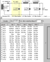
Yeah, that's basically what I did except that I added resistance between the rectifiers and the first cap but the results would be the same.

There is some discrepancy between my PS schematic and PSUD because my schematic voltages are measured with the variac set to 122v, which is about what my wall voltage normally is. I think PSUD assumes that wall voltage is 120v so I think I set the variac at 120v and then adjusted the resistance until the B+ in PSUD matched the B+ I measured. I did this quite a while back so I don't recall if there might have been any other minor changes made since then. The ESR of the film caps is probably lower than what I entered too. So there are certainly some fudge factors involved.

This seemed like the practical way to do it since I knew the measured B+ was accurate.

I'm still not sure about the accuracy but the amp is totally quiet, which is all I care about. For whatever it's worth, here's what it showed:

45-75-150 PS.png
 
So it looks like it modeled 6v lower than actual? Id call that close enough at these voltages.
 
Back
Top Bottom
