• The move to the new server is done. There are some software and database maintenance updates in process. This has us passing the hat around to help out. We appreciate any donations. Seriously, even a dollar helps. The payment page may be found here - https://www.audiokarma.org/support.html

Grado Wood Tonearm Pivot

audioclassic

New Member
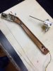
I am in the process of reworking a Grado wood arm for use on a Rek O Kut project. The arm has been disassembled, everything cleaned up and ready for reassembly and install on the table. One question I have: The arm has a notch at the back that rests on a horizontal rod inside the aluminum housing. All the photos I've been able to find of original appearing arms have a notch as opposed to a hole bored through them that the rod passes through or sits on. • Is the notch correct or was this originally a hole bored through the arm for the rod to pass through?

Is the rod glued in the tonearm notch/hole?

This arm was repaired many years ago. The repair was done well and the screws are almost an improvement as reinforcement to a weak spot in the arm's design. I can leave this as is or repair it if a through hole is actually correct. But still need to know if the rod was glued in place or not.
 

Attachments

  • IMG_5731.jpg
    IMG_5731.jpg
    73.5 KB · Views: 52
Last edited:
Register to hide this ad
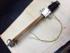
I found two owners who had three original arms between them. The notch is incorrect, should be a hole bored through for the rod which makes a lot more sense from a design and engineering standpoint. Did the repair last night, replaced the old fix with a new piece of wood drilled to accept the pivot rod. Will stain to match. Decided to rewire the arm next.
 
The finished arm. Rewired using a shielded set of tonearm wire from a parts deck. The shield was trimmed at the back of the tonearm and connected to a more flexible yellow wire for ground.
IMG_5753.jpg
 
Love to see the underside where the cable is run. What gauge is this? The original is not directly replaceable. Nice work here.
 
Thanks. I would have to check the wire gauge to be sure, 34 AWG? The ground wire is slightly heavier. The original channel where the wire runs was more than deep enough for the replacement wiring and the outer wire insulation made for a nice friction fit. I did a quick test of arm movement with the arm in place and I think it will be fine. My worry was connecting the new wire to the cart sled contact points . Turned out to be very simple. Continuity checked and all is good.IMG_5751.jpg
 
Can you explain a bit on how you removed the plastic piece attached to the arm with wires and got it assembled and back into position? The piece the sled connects to. I need to do the same sometime. My wiring is pretty sketchy. It’s the original.
 
Can you explain a bit on how you removed the plastic piece attached to the arm with wires and got it assembled and back into position? The piece the sled connects to. I need to do the same sometime. My wiring is pretty sketchy. It’s the original.
I didn't remove the plastic connector. This arm had been rewired at some point, many years ago I would guess, and wire was not in the best shape. I removed those wires and the glue they were set in at the plastic connector, then simply soldered the fresh set to the sled connect points staying off to the side of the brass points (the brass dots). I was afraid if I made the connection in the center of the brass there may be some interference with the fit and connection of the cart sled to the connection points.
 
Here you go MRL_Audio. This is before I cleaned things up. The glue and old wires are gone but you can see the dark area in the plastic, around the brass cart sled connectors, where the original wire attached. The ground wire from the brass plate was shorter than I would have liked and connecting to the shield wires was tougher especially since my soldering skills are rudimentary at best. But it works just fine and keeps the original cart sled. I know others like to eliminate the connection points and run their new wires straight to the cartridge pins. I figure that's always an option down the road if this setup fails. I added a spot of glue to the new wires to keep them in place, just like the originals had, and moved the ground wire off to the side and insulated/glued it in place too.
cartconnect.jpg
 
Back
Top Bottom