• The move to the new server is done. There are some software and database maintenance updates in process. This has us passing the hat around to help out. We appreciate any donations. Seriously, even a dollar helps. The payment page may be found here - https://www.audiokarma.org/support.html

Gray Research AM-50 / Dynaco Mark 2 Clone / Gray Concert Duet Console Info Questions Schematics?

Jxmos

Member
At an auction last fall, I was lucky enough to win a Gray Research amplifier and preamp. Since information on these is hard to find, I thought I share what I’ve found and see if others might have more details.

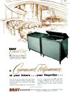
As I restore them, I believe these are units from a console that Gray Research sold in 1956 called the ‘Concert Duet’. I’ve found references to the Gray AM-50 being sold as a standalone amp as well. The Mullard EL34’s appear to be original and are still test very strong. Since these are metal base examples, I’ve set them aside while I restore with other more common EL34 tubes. Unfortunately, the rectifier was bad and needed to be replaced, but that may have saved the output tubes. I founded the amplifier with a 20 AMP fuse installed instead of a 4 amp. It’s surprising that the transformers are still good, but they seem to be working well so far.

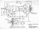
The Gray AM-50 is a clone of the Dynaco Mark2 with a few variations. Although I don’t have a schematic for either Gray unit I can see the amp is an early design of the Dynaco Mrk2 amplifier.

The Gray transformers are marked on top. The power transformer is marked TR-5000 while the output transformer is marked TR-5001. I assume these are Dynaco transformers since the wire colors match the Mrk2 schematic. Most of the red colored wire coming from the transforms has faded to more of a yellow color. Other than that the wires and connections are a match.

The PCB is obviously a Gray manufacture part and it’s mark with “Gray Research and Development Part No. PC-0001-B” on the solder side. All the eyelets and jumper wires match the Mrk2 PCB.

There are early schematic versions of the Mrk2 that did not include a cathode resistor. That’s the case with the Gray AM-50, it didn’t have a cathode resistor either. So I’ve added a 12 ohm 1% 1W resister for measuring the output tube bias. I’ve also updated the 1.2 M ohm to a 1.5M ohm resistor attached to pin 7 of the 6AN8 tube.

The rectifiers are different between the two amps. Gray used a 5AR4 while the Mrk2 uses a 5U4. The Gray also has a different filter cap design. I’m wondering if I should change the Gray design? For the first filter cap, Gray used two 40uf 350v caps in series with a 100k ohm resistor across each cap. This is effectively a capacitance 20uf 700v I believe.

filter_caps_1.jpg

The Mark 2 used one 30uf 500v cap with no resister (Mrk3 with its 5AR4 has no resistor either)


filter_caps.jpg


So, which is the better filter design for a 5AR4 rectifier? Two 40uf caps in series or one 30uf cap?

The AM-50 is working. All the components on the PCB were out of spec except the two rectangular caps. I've restuffed the quad can cap with new 20uf 500v capacitors. The 2 40uf 350v caps are original but I'm checking them frequently.

The amplifier is wired to supply power to the Gray mono preamp and I’ve just started looking at this unit. The preamp doesn’t appear to be a Dynaco clone but maybe a Heathkit WA-P1 clone. The only marks on the Gray PCB are PR-1. I’ll need to spend more time tracking connections to see if they match. Another bonus, the preamp came with 2 Telefunken 12AX7 ribbed plate tubes.

If anyone has copies of the schematics or manuals for the Concert Duet, AM-50 or the Gray preamp, please let me know. Also, please share your thoughts on the filter caps.
 

Attachments

  • ConcertDuet ad2.jpg
    ConcertDuet ad2.jpg
    130.7 KB · Views: 64
  • ConcertDuetad1.JPG
    ConcertDuetad1.JPG
    105.9 KB · Views: 60
  • GrayPre1.jpg
    GrayPre1.jpg
    37.2 KB · Views: 61
  • GrayPre.jpg
    GrayPre.jpg
    47.2 KB · Views: 63
  • GrayAM50Bottom.jpg
    GrayAM50Bottom.jpg
    128.7 KB · Views: 62
  • Gray_AM50.JPG
    Gray_AM50.JPG
    69.2 KB · Views: 65
  • Mrk2_schematic.jpg
    Mrk2_schematic.jpg
    90.2 KB · Views: 71
Last edited:
Register to hide this ad
Interesting to read about your find. Congratulations. I have not heard of Gray amplifiers, so I’m speaking in general terms about your question re. the power supply.

Some would advise to keep it original for collectors value (5AR4 with two series 350 V input capacitors. Gray was wise to use the effective 700V ability for the input cap together with the 5AR4. Dynaco used a 525 V input cap on the Mk3 with the 5AR4 rectifier, and from experience I know that is a slim margin of safety during the startup surge. I would not use a 500V first capacitor with a 5AR4.

If your Gray power transformer is indeed the same as the Dynaco P-782 on the Mk2 and 3, and you need to do work on the power supply, I would build it like the Mk3 supply with an appropriate choke instead of the power dropping resistor and an appropriate input capacitor. If you don’t have an appropriate voltage multicap for the first cap, I would use a higher voltage single capacitor since such caps are available now, such as https://www.mouser.com/ProductDetail/KEMET/ALC70A510BB600?qs=PqoDHHvF64/RmfuGjc4jNg==. I would still provide the 2x100k resistors as bleeders, which the Mk2 apparently lacks.
 
Thanks guys. I'll leave the original 40uf caps in place. I have noticed a concern once the amp was powered up. The large can holds 4 20uf caps and the can is marked 500v for each. So, I used the same rated caps to replace the originals. Now I wish I had gone higher. At 117vac, I'm seeing 510v on the plates and 6.2vac on the filaments. I hope I wouldn't have a problem with an under rated capacitor.
 
@Jxmos,

If the Grays were mine I would be uncomfortable with 510 Vdc on a 500 V rated multicap. I would address the issues in the power supply and install the choke option in place of the 50 Ohm 10 W resistor, such as: https://www.digikey.com/en/products/detail/hammond-manufacturing/156R/454888 Looks like you should have plenty of room in your chassis. (The Grays, like Dynaco Mk2, were stingy with the power supply to meet a price point, and lack sufficient capacitance and inductance. Mk3 was a modest move in correcting that deficiency, but with modern capacitors relatively cheap you could do more to get the best out of those fine transformers).

Other issues in my view is the lack of series resistance between secondary and rectifier. Modern 5AR4s do not hold up as well as NOS without the datasheet specified series resistance(s) between the transformer secondary and the 5AR4 anodes. NOS 5AR4 were often used incorrectly used, yet survived because they exceeded the specs. (To wit, your original rectifier did not survive; what are you using now?) See Charts III on page 3 of: https://frank.pocnet.net/sheets/093/5/5AR4.pdf (If you are ambitious you can measure the parameters, calculate and install the correct value Rs resistors - I would do the “interim” first and see)

As an interim measure you might move your 50 Ohm 10 watt resistor to follow the rectifier, before the dual 40 uF caps, and install the “yellow-sheet mod” for good measure. (My very first tube amplifier. Excited! ) With these measures your B+ should be at or just below 500V at normal operation.

I recommend, to deal with the turn-on surge, that you disconnect the first 20uF cap in the multican and in its place install the 600 V snap in capacitor I linked above. As second cap (after a choke) you could increase the capacitance even more, to say 120 uf. Personally I would replace the first cap also (capacitance can not exceed 60 uF for 5AR4) with the 600 V rated cap. (You can add the unused 20uF to the phase splitter supply)

Good luck and happy listening.
 
Last edited:
Yes, I agree. I need to install a choke. I see the new Dyanco choke c-354 is shielded. I assume a shielded choke is better than a non shielded? And is the shielding for containing RF or keeping RF from affecting the choke?

I'll also redo the can cap with higher rated caps.

I'm using a RCA 5AR4. I'm not sure of its birth day but it's marked xFY under RCA and made in Japan. The date code appears to be missing a character before FY. The box is 'newish' so I'll assume the tube is from the 1970s.

As a test, I lowered the input volage to 110vac and the plate volage dropped to 494vdc with the filament voltage at 6.0vac. With a 6v filament voltage I believe that's to close the lower range, so increasing the filter cap ratings and adding a choke seems the best option.

Thank you!
 
I might recommend the Triad C-24X, slightly lower inductance but higher current rating. Fits in the same location and dimensions. I used it in my Mk2's. I seem to remember that the original has a slightly too small current rating.
 
Thanks @nerdorama, I'll check it out.

@spantou01 You mentioned increasing the capacitance to 120uf but also said the 5AR4 is limited to 60uf max. Is the 60uf limit for the first cap only?

I've noticed that Gray added a cap to their can for use in their preamp. Here's a graphic:

filter_caps_total.jpg

I don't see the last 20uf cap for the preamp in the schematics for the Mrk2 or Mrk3. If it's proper to just added the capacitors, the Gray has 100uf of capacitance? How would this string of caps impact the 5AR4s max capacitance?
 
@spantou01 said 120uF after the choke so that's assuming you replace the 50 ohm resistor with a choke. Keep the first cap lower and within the ratings of the 5AR4. I think the datasheet says 60uf max but I might go even lower to around 40uF to keep the charging current surges down. With the larger cap after the choke you don't need max capacitance in the first cap.
 
The max cap size is also heavily influenced by source resistance and voltage. No reason to push the limits here, the CLC filter setup will give you good clean voltage even without a huge first cap.
 
I agree with @nerdorama on being conservative on the first capacitor, and the one I linked in post #2 is 51 uF, which should be acceptable IF you install the calculate Rs from the 5AR4 datasheet, or the 50 Ohm before the fist capacitor. (I did not search very hard but could not find a 600V electrolytic at Mouser with ~40 uF.)

My suggestion was that a 120 uF 600V capacitor could be used after the choke (second capactitor), instead of the one section of the 20uF 500V multicap. The latter you could used in paralel with the capacitor feeding the first 6AN8 section (phase splitter.) The caps down the line are usually not exposed to the surge and since there are high resistors in series they do not contribute to the initial current demand which is the nemesis of tube rectification.
 
Ok, I think I have it. The 5AR4 capacitance max limit refers to the first cap directly connected to the rectifier (before a resistor or a choke). The remaining caps are not considered.

So, I'll need to replace the two series connect 40uf 350v (20uf 700v) first cap with a 40-50uf 600v cap and keep a bleeder resistor. Plus replace the 50ohm 10w resister with a choke and increase the second cap to as much as 120uf 600v.

Thank you all for offering up your knowledge!
 
filter_caps_total-jpg.3712458


This design relies on the 100K-ohm resistors distributing the voltage load equally between the two 40 mfd/350 VDC caps. If they don't, you won't get the calculated net value or even wear on the caps.

I always go with a single cap, near-equivalent to the two-series caps, if possible. After all, this series design was a compromise due to the lack of an affordable single equivalent cap at the time of manufacture.

20mfd/500VDC or greater, VDC rating is fine. Check the size to be sure you won't have a fit issue. These 600VDC caps are long (almost 4 inch body, plus the lead lengths). [Really, a good quality 500VDC will be fine].

If you want to keep the series-cap layout, try using high-quality metal-oxide resistors (I like 2-watt, 5% tolerance, if possible) and fresh 40 mfd/350 VDC caps. :thumbsup:
 
Last edited:
So, I'll need to replace the two series connect 40uf 350v (20uf 700v) first cap with a 40-50uf 600v cap and keep a bleeder resistor. Plus replace the 50ohm 10w resister with a choke and increase the second cap to as much as 120uf 600v.

Exactly.

Plus move the 50 Ohm 10 watt resistor to connect the rectifier and the first cap to serve in lieu of a properly designed series resistors (Rs) as prescribed by the datasheet linked in Post #5. Note, the Dynaco Mk2 used a 5U4 rectifier with more voltage drop than the 5AR4. Your RCA Japan-made 5AR4 sounds like an NEC or Toshiba, and those are tough, so expect long and good service if you treat it right.

20mfd/500VDC or greater, VDC rating is fine. Check the size to be sure you won't have a fit issue. These 600VDC caps are long (almost 4 inch body, plus the lead lengths). Really, a good quality 500VDC will be fine

Those axial Sprague Atoms are good caps and I have used many of them 20-30 years ago, but better, cheaper and smaller caps are available now in like or higher capacitances and voltages. Notice the Atom spec is only for maximum operating temperature of 65°C. (Check out the capacitor I linked in post #2.)

I disagree that “a good quality 500VDC will be fine” in the first two capacitor positions where @Jxmos measure the quiescent voltage of 510 V at the second capacitor.
 
Last edited:
OP is trying to get the B+ voltage lowered to be like a Dynaco Mk3 at around 490 V. The Gray amp is probably biased like a Dynaco Mk2 for about 130 ma.
 
Last edited:
At an auction last fall, I was lucky enough to win a Gray Research amplifier and preamp. Since information on these is hard to find, I thought I share what I’ve found and see if others might have more details.

As I restore them, I believe these are units from a console that Gray Research sold in 1956 called the ‘Concert Duet’. I’ve found references to the Gray AM-50 being sold as a standalone amp as well. The Mullard EL34’s appear to be original and are still test very strong. Since these are metal base examples, I’ve set them aside while I restore with other more common EL34 tubes. Unfortunately, the rectifier was bad and needed to be replaced, but that may have saved the output tubes. I founded the amplifier with a 20 AMP fuse installed instead of a 4 amp. It’s surprising that the transformers are still good, but they seem to be working well so far.

The Gray AM-50 is a clone of the Dynaco Mark2 with a few variations. Although I don’t have a schematic for either Gray unit I can see the amp is an early design of the Dynaco Mrk2 amplifier.

The Gray transformers are marked on top. The power transformer is marked TR-5000 while the output transformer is marked TR-5001. I assume these are Dynaco transformers since the wire colors match the Mrk2 schematic. Most of the red colored wire coming from the transforms has faded to more of a yellow color. Other than that the wires and connections are a match.

The PCB is obviously a Gray manufacture part and it’s mark with “Gray Research and Development Part No. PC-0001-B” on the solder side. All the eyelets and jumper wires match the Mrk2 PCB.

There are early schematic versions of the Mrk2 that did not include a cathode resistor. That’s the case with the Gray AM-50, it didn’t have a cathode resistor either. So I’ve added a 12 ohm 1% 1W resister for measuring the output tube bias. I’ve also updated the 1.2 M ohm to a 1.5M ohm resistor attached to pin 7 of the 6AN8 tube.

The rectifiers are different between the two amps. Gray used a 5AR4 while the Mrk2 uses a 5U4. The Gray also has a different filter cap design. I’m wondering if I should change the Gray design? For the first filter cap, Gray used two 40uf 350v caps in series with a 100k ohm resistor across each cap. This is effectively a capacitance 20uf 700v I believe.

View attachment 3711846

The Mark 2 used one 30uf 500v cap with no resister (Mrk3 with its 5AR4 has no resistor either)


View attachment 3711848


So, which is the better filter design for a 5AR4 rectifier? Two 40uf caps in series or one 30uf cap?

The AM-50 is working. All the components on the PCB were out of spec except the two rectangular caps. I've restuffed the quad can cap with new 20uf 500v capacitors. The 2 40uf 350v caps are original but I'm checking them frequently.

The amplifier is wired to supply power to the Gray mono preamp and I’ve just started looking at this unit. The preamp doesn’t appear to be a Dynaco clone but maybe a Heathkit WA-P1 clone. The only marks on the Gray PCB are PR-1. I’ll need to spend more time tracking connections to see if they match. Another bonus, the preamp came with 2 Telefunken 12AX7 ribbed plate tubes.

If anyone has copies of the schematics or manuals for the Concert Duet, AM-50 or the Gray preamp, please let me know. Also, please share your thoughts on the filter caps.
darn nice looking mono blocks, keep you eyes open for another mono block in good looking condition. I looked for 20 years for one Stromberg Carlson AP-437 then late last year there was one NOS in original box so i got that one, just after that another one NOS in original box came up and i got that one too...1960-1 im listening to Van Morrison right on through them . have a tech go through it before you plug it in...oh the smell of the amps is like so great....not a bad smell just great..
 
Last edited:
So a guy who's been bringing me weird stuff to repair brought me a couple Gray preamps and what looks to be the power supply
Some quick searching led here, is there any info on the power supply around?

It's got a couple huge power transformers, another big rectangle that's labeled as two 4 Henry coils?
One 5V4 rectifier tube, selenium rectifier, and what looks like a choke or other transformer
Two plugs for the preamps and an octal plug that's probably the output.

Talk about over built!
 
Well they're going to live, they all need work but function
Anyone have a schematic for the AM-3 preamps?
The mag phono inputs were disconnected and wiring to the mag 1/2 switch removed
Thanks
 
Work on my Gray AM-50 is on the back burner at the moment. I needed to address the 'honey do' list. :)

I've not found any schematics for Gray's amp or preamps. But I believe they started with Dynaco designs and tweaked them for their own needs. I've seen pictures of the Gray AM-3 from the outside and perhaps the Dynaco PAM-1 was a starting point for them? Schematic attached.
 

Attachments

  • PAM-1 PowSup Schematic.JPG
    PAM-1 PowSup Schematic.JPG
    38.1 KB · Views: 8
  • PAM-1 Schematic.JPG
    PAM-1 Schematic.JPG
    90.1 KB · Views: 8
Back
Top Bottom