• The move to the new server is done. There are some software and database maintenance updates in process. This has us passing the hat around to help out. We appreciate any donations. Seriously, even a dollar helps. The payment page may be found here - https://www.audiokarma.org/support.html

Griffins tapered line array wiring

Oliver2000

New Member
dear all,

i am joining with a question that is probably simple for many of you but i werent able to figure it out.

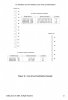
i was trying to make a concrete wiring diagram of james giffith’ s tapered line array example that he mentiones in his great 2003 paper and of which i join the relevant page here.

can anybody help me with that, please? i seem to be getting all sorts of short circuits as you need to do multiple series and parralel wirings to the same speakers in the array.

many thanks in advance for your help. guess this is also interesting for other people.

best wishes to all members

oliver870BD44F-E022-41B5-A429-C338279CB00F.jpeg
 
Register to hide this ad
many thanks for this suggestion. we will attempt to do that but had some issues registering on their website. we also tried to contact dr griffin directly but the email address in his paper is no longer valid. that is why we were hoping to find an answer here.
 
What I would suggest Oliver is that you draw the coils of the speakers in a fashion that your comfortable with. Like either a circle with + and - on each side...or a couple loops to represent each driver and then again label the terminals. Study and make sure it makes sense and is correct.

You may find if you draw it another time and line up some drivers together that it makes more sense. For instance, groups of drivers in a line that go in series. Then write in for one line (8 ohm drivers X 4) the number for that line...and then the same for the next series. Then write bigger off to the side the total of the two lines being half of the single line value. This not referring to your project, but just in general.

Then do another drawing with more of a vertical line that is more like the physical array. Have the + and - on the drivers mimic the way they actually sit.

This helps get it worked out from the paper drawing to the physical in front of you. Having made a long line speaker system myself, I've reached that point of starting to get confused about things as you start to wire. Trying to use red and black wire (or terminal color) and they cross places that doesn't work right for as one end is plus and the other negative and it's easy to start getting your thinking messed up. But, if you've laid it out on paper correctly, then you can refer back to its lines and get it back straight again. That large number of drivers and wires can get less clear as you go if you don't have something that you can physically work from referring back and forth from paper drawing to the physical in front of you.

Hope that makes some sense and perhaps helps! Good luck with the project!

EV3
 
thanks ev3.

thats what i have been trying to do for the last cpl of weeks. but i dont seem to get it right.

would you mind just posting one diagram for example of the first two uniform feeds (group of three and four speakers in series) only from the page i posted? that would be very helpful.

best wishes

oliver
 
hi - here to illustrate the issues.

if i want to connect the same 12 chassis in 3 groupes of 4 in series and simultanously in 4 groups of 3, then we basically need to connect them all in one long series and connect the groups of three and four to the positive and negative wires.

we then get shorts an cases where one chassis is connected directly to plus and minus. this doesnt seem right. anybody please point us to the mistakes and explain how to do it right.

many thanks856CF9E4-5758-4034-93B4-1493DED58F48.jpeg
 
i was trying to make a concrete wiring diagram of james giffith’ s tapered line array example that he mentiones in his great 2003 paper and of which i join the relevant page here.

can anybody help me with that, please? i seem to be getting all sorts of short circuits as you need to do multiple series and parralel wirings to the same speakers in the array.
Hello Oliver. Welcome to AK.

Please forgive me if I misunderstand your question. The chart on the page you posted shows only 4 options for wiring 12 woofers in Series/Parallel.

line-array_chart.jpg

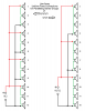
Both of the Uniform Feed options simply connect in Parallel equal groups of Series woofers:

Uniform feed line array c.png

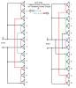
Both Tapered Feed options connect in Parallel non-equal groups of Series woofers, but with the groups positioned symmetrically so top half mirrors the bottom half.

Taper feed line array c.png

None of these options shown on the chart connect woofers in 3 groups of 4 in series, simultaneously, with 4 groups of 3 in series. Is that something Dr. Griffin wrote about elsewhere in the paper?

I can only see this being possible if each woofer has 2 voice coils. Then one voice coil of each speaker could be wired in 3 groups of 4 while the other set of voice coils is wired in 4 groups of 3.
 
Last edited:
dear stuart, many thanks for your message.

i was actually presuming all of these connections had to be done SIMULTANOUSLY to get the desired impedance but i maybe wrong, actually. if its like you say, then i have learend my lesson on speaker wirings… :bowdown::bowdown::beerchug::banana::jump:

can somebody please confirm that i totally misunderstood dr griffins paper?

best wishes
 
dear stuart, many thanks for your message.

i was actually presuming all of these connections had to be done SIMULTANOUSLY to get the desired impedance but i maybe wrong, actually. if its like you say,

can somebody please confirm that i totally misunderstood dr griffins paper?
On page 21 of the paper, in the section titled Example of Driver Combinations for a Typical Line Array Application, the chart of Fig.12 is introduced as examples of different line array types. Referencing the chart, Griffin compares 4 parallel groups arrays to those with 3 parallel groups:

"The various possibilities include uniform and tapered feeding configurations for the 12 woofers and 6 tweeters are illustrated in Figure 12. Note that for the 12 woofers case that the 4 parallel group combinations will have a slight sensitivity edge versus the groups that have only 3 parallel paths."

Which seems to suggest that each line of the chart is meant to represent a separate array configuration.

Griffin's paper is a great read. I've downloaded it to study at greater depth as I find time. Thank you for bringing this to the attention of those of us who were not aware. :thumbsup:
 
many thanks stuart, you are 100% right. i had aloso checked but couldnt post a message for some reason.

not very smart on my part but i learned a lot from this.
 
Back
Top Bottom