• The move to the new server is done. There are some software and database maintenance updates in process. This has us passing the hat around to help out. We appreciate any donations. Seriously, even a dollar helps. The payment page may be found here - https://www.audiokarma.org/support.html

Ground hum, Yamaha C4

Hifibythekg

Super Member
Have nearly tracked down the source of a constant loud hum.

Think it’s the Phono MC input.. So, am wondering what should I especially check in the area of the Phono MC RCA inputs and pcb?

Some background:

Inserting a shorting plug into the MC Phono inputs has a modest effect on the volume of the constant hum.

Inserting an RCA interconnect cable (with nothing attached at the other end) makes a very much louder hum, it also causes a bit of of electrical connecting crackle. This effect is equally strong through both channels.

Doing the same actions on MM1 and MM2, Aux and Tuner has no effect whatsoever on the hum.

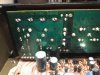
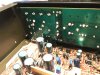
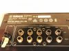
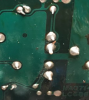
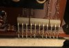
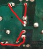
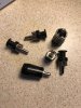
Perhaps the MC phono inputs were replaced or repaired previously.. can anyone tell from these photos? There’s a slot in the RCA’s black centre that isn’t present on the MM’s.

Also, have double checked every solder join on the amp, operated every switch and tapped the board, wafer switches and caps all over and it doesn’t generate any odd sounds or have the slightest effect on the consistent tone of the hum.
 

Attachments

  • E1B7C0D8-D5B2-45DC-B225-811BFA531140.jpeg
    E1B7C0D8-D5B2-45DC-B225-811BFA531140.jpeg
    128.7 KB · Views: 23
  • D75F1653-0120-46C7-9B94-72446903F2FF.jpeg
    D75F1653-0120-46C7-9B94-72446903F2FF.jpeg
    109.4 KB · Views: 22
  • 5C1930ED-DD79-4A6B-88B6-18C4A304C7E9.jpeg
    5C1930ED-DD79-4A6B-88B6-18C4A304C7E9.jpeg
    126 KB · Views: 24
  • 813D01A3-732E-4DE9-846C-7E8A65D404C2.jpeg
    813D01A3-732E-4DE9-846C-7E8A65D404C2.jpeg
    97.5 KB · Views: 21
Register to hide this ad
Do a continuity check on the Phono 3 MC jack solder connections..

upload_2021-12-20_16-17-6.png

Also check your solder connections for the RCA jack board to the main board.
 
So..
Hum still present, mostly on left channel.
Loudest on MC Phono.
Disconnected the RCA pcb to check it over.
While powered off, the other phono sockets are zero on the DMM’s Diode test mode and beep.
The MC phono solder points measure 835 ohms on each channel.
About to check and replace the caps as you mentioned previously.
But is there any other check or measurement I could do at this time?
E7212607-12FE-41E9-97B5-D26A2771320E.jpeg
 
So..
Hum still present, mostly on left channel.
Loudest on MC Phono.
Disconnected the RCA pcb to check it over.
While powered off, the other phono sockets are zero on the DMM’s Diode test mode and beep.
The MC phono solder points measure 835 ohms on each channel.
About to check and replace the caps as you mentioned previously.
But is there any other check or measurement I could do at this time?
 
Thanks Dave.
Ha, the solder lug with the bit of copper showing just snapped and flicked off the board as the probe touched it!
However, even with the RCA module taken off behind it there's still the same hum!
I'm racing to get an order in for the caps you recommended replacing, still make sense to do this?
 
Has anyone got a legible circuit board file they could share?
Mine is virtually illegible and is making it hard to identify caps.
 
Was too late to get an order in so checked all the caps on the left channel Most were well within spec and only replaced a couple to see if this would make a difference.

Well, the hum is still present but clearer and better balanced on tleft and right channels now!

At this point in time hum is:

Equal volume across all INPUT selections.
Equal volume in both Left and Right channels.
Louder via Phono MC.
Tapping PCB and turning switches, touching inputs etc has no effect on the hum, no props or crackles.

Headphone socket..
Headphones get no signal unless volume for speakers is turned up a little, at this point the volume pot for the headphones works fine.
There is hum through the headphone socket as well.
 
Tapping mostly caps in the gloom of the Flat Amp circuit board, managed to tap the TR421 attached to the chunky heatsink. Sound immediately cut out and this fuse is blown. Its solder points and neighbouring components' solder points also, seem fine on the other side.
What should I do. Reflow solder, change fuse and power on?
Or is there a better way to proceed?
 
Tapping mostly caps in the gloom of the Flat Amp circuit board, managed to tap the TR421 attached to the chunky heatsink. Sound immediately cut out and this fuse is blown. Its solder points and neighbouring components' solder points also, seem fine on the other side.
What should I do. Reflow solder, change fuse and power on?
Or is there a better way to proceed?
What were you tapping with. Those two heatsinks are each have 42 volts on them..
 
A wooden spoon. It was actually the 'solo' heatsink and transistor, not one of the pair of heatsinks but I take your point, and thanks for the info.
But where best to go from here.
Fwiw, the amp sounded excellent with music through it into a NAD 3020 power section and some Radio Shack Minimus speakers for testing.
 
I didn’t think it did. Not next to the unit right now but will check soon. Two different consequences I guess..
Well-informed question though, would expect nothing less.
 
Just checked. Don’t think I tapped it sufficiently hard that it touched the heat sink, although it is a possibility. Certainly, though, it was the cause of shutting the unit down and blowing the fuse in the previous photo.
 
Back
Top Bottom