
• The move to the new server is done. There are some software and database maintenance updates in process. This has us passing the hat around to help out. We appreciate any donations. Seriously, even a dollar helps. The payment page may be found here - https://www.audiokarma.org/support.html

Grounding both chassis and earth for a new tube kit and heater voltage question

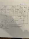
Hello all, i am sure this has been asked many times. i am starting a new kit, using 203 power tube, including the Chinese schematic. i want to be sure outside grounding the IEC socket to the chassis which would be connected to earth here in the USA 120vac. but want to be sure should the center tap for the heater and high voltage be also connected to earth ground, or chassis ground. in last kits i did so, and only the power supply, and al other caps and resistors to chassis ground. ultimately, isn't both chassis ground and the ground wire from the IEC ground all connected to chassis ? the symbol for ground is vague.
thanks again for advice.
Chuck.
 

Attachments

  • 203 TUBE KIT schematicIMG_0395.jpg
    203 TUBE KIT schematicIMG_0395.jpg
    50.7 KB · Views: 28
Register to hide this ad
sorry the 2nd part of question, the schematic for the 807 tubes mention to Groupe 2 of the 6.3v to use on fu-26 /807 and to join together. the 807 states to have a 12v ac. my question is can i run the heaters of the 807's on 6 vs ?
 
Im no expert but if a earth ground is connected to your phone, cable, electric, antenna or whatever. Any of those utilities that has a problem with a power spike could cause problems. All wall outlets should already have a earth ground. I’d look into some type of surge protection. I’m sure others will chime in that knows more about it than me. Good luck
 
807's are 6.3V

Chassis safety ground is near IEC, no other connections.
Circuit 0V is tied to first power supply cap chassis connection for stereo amps. You can use wires to star grounding points or a bus ground scheme.
Of course this is just one way of doing it, some are successful with multiple 0V connections and others use a single point as above for low noise.

Link for some good ground information (focus is on mono amplifiers, so not everything applies to stereo amps).

Video on bus ground, can be adapted to use regular wire instead of bus.


Heater/filament grounds.

 
Last edited:
thanks all, ill check out the video's. what i have been doing for grounding on the other 4 kits i built, has been use a grounded power cord, to my wall, which is good ground. so the ground wire from IEC bolts to chassis about 1~2 inches from inlet. i then use a copper 12ga buss which is also bolted to the chassis close to the DC power supply close to power transformer, from this i connect all my power supply filter caps, and any other components like resistors to ground. the HV and any other Ov taps on the transformer are connected to the ground part that connects to the ground lug of IEC socket. of course, single phase 120 ac power from panel is share neutral and ground buss, but my house, newer construction has an ground stake out side by the underground power and meter. ALL this i want to Know is this the safest best way to ground, and also best to eliminate ground loops/ noise.
thanks.
 
someone mentioned that the 807/ FU-25 tubes are 6.3v heater, just curious, per the wiring schematic see (picture) does it state " for FU-25 filament voltage 12.6v, use 2 groups of 6.3v in series to form 12.6v. NOTE the power transformer has 2 sets of 6.3v windings/taps. i feel better using 6.3 v for 807 tube. will it work proper.
thanks.
 
Chassis safety ground is near IEC, no other connections.
^^^ This. I never had a problem mixing grounds until I restored my Citation V. It was clean on the bench, but produced a hum in my system after adding a three-wire AC cord. I tested by isolating the earth prong on the AC plug temporarily, and the hum disappeared. There are various techniques for eliminating this problem, also known as "breaking" the ground loop. In my case, I had initially wired all the signal/power supply grounds to a short bus wire soldered between two terminal strips. It was a simple matter to lift the entire bus off the chassis so that only the chassis itself is now connected to AC earth. Problem solved.

Jack
 
Last edited:
A poorly connected ground bus is as bad as the worst multi-point chassis grounding scheme. Connect center-tap of transformer to the same point as the negative terminal of the first filter cap and the largest hum source is gone. If there's no noise current flowing in the chassis, then grounding to the chassis anywhere is fine. Most vintage amps were hum-free because their designers understood this, and bus or star grounding would not have made them better. There are some more subtle hum sources that can be hard to find, such as the magnetic field induced by the power transformer. But there's a physical cause and understanding the physics can help fix it.
 
A poorly connected ground bus is as bad as the worst multi-point chassis grounding scheme. Connect center-tap of transformer to the same point as the negative terminal of the first filter cap and the largest hum source is gone. If there's no noise current flowing in the chassis, then grounding to the chassis anywhere is fine. Most vintage amps were hum-free because their designers understood this, and bus or star grounding would not have made them better. There are some more subtle hum sources that can be hard to find, such as the magnetic field induced by the power transformer. But there's a physical cause and understanding the physics can help fix it.
Just to be clear, none of this is applicable to the Citation V that I mentioned. It's essentially a star ground as-is, with only one or two points in the power supply being connected to the chassis. All the driver circuitry and related is connected back to those grounds. And I don't agree that "grounding to the chassis anywhere is fine." Noise current is only one of the issues; multiple grounding points risk a multitude of problems, including oscillation. Yes, much of the older equipment with a two-wire line cord took advantage of the chassis for grounding, but in all cases the higher current grounds, such as those produced by the B- to the output tubes, doesn't cross the same geographic area of the chassis as the smaller currents created between preamp tubes. It's also worth noting that comparing the OP's process to a commercial unit without applying best practice is very risky. Factories build prototypes - both in sections and in whole - in order to weed out accidental grounding problems. Those of us who build our own don't usually have that luxury, so we need to follow methods that are more universally guaranteed to produce a good amplifier the first time. These methods seem to be better published on the many DIY guitar amplifier forums than here on AK, probably due to the need to keep high gain input circuitry stable and noise free.

Jack
 
Oh, I was not talking about the Citation - I was pointing out that just tying every ground to a bus isn't enough - you have to be aware of where the noise current are, and minimize any current loops in those areas. Put all the power supply connections at one end and everything else becomes less critical. A long winding ground bus is probably worse for oscillation than grounding circuits locally to the chassis. Having worked with RF power amplifiers for 45 years taught me a lot about stability. And I learned that many parts that give trouble aren't on the schematic - ground resistance, stray inductance and capacitance, magnetic coupling, power supply impedance, etc.

Yes guitar amps are much touchier than power amps, but having a separate preamp and amplifier chassis introduces its own challenges.
 
Oh, I was not talking about the Citation - I was pointing out that just tying every ground to a bus isn't enough - you have to be aware of where the noise current are, and minimize any current loops in those areas. Put all the power supply connections at one end and everything else becomes less critical. A long winding ground bus is probably worse for oscillation than grounding circuits locally to the chassis. Having worked with RF power amplifiers for 45 years taught me a lot about stability. And I learned that many parts that give trouble aren't on the schematic - ground resistance, stray inductance and capacitance, magnetic coupling, power supply impedance, etc.

Yes guitar amps are much touchier than power amps, but having a separate preamp and amplifier chassis introduces its own challenges.
I agree, and the concept of keeping PS and high current grounds at one end, with small signal grounds at the other, is a good technique. The ground bus I installed in the Cit V was tinned #16 and only about 3" long. The long wall-to-wall bus wires I've seen in some commercial gear were generally located in the small signal areas around tone controls and line-level circuitry, and they weren't carrying heavy current. We probably have some common experiences; most of my professional work for the last 35 years or so was RF. My last position before retiring dealt with extremely low phase noise circuitry (oscillators and small signal amplifiers). Some of those products went to Mars. Anyway, I was just trying to point out for the OP that isolating all the grounds from the chassis is one means of eliminating the possibility of a ground loop with external equipment. If it's a star ground, so much the better. I've gone to the trouble of connecting each stage of sensitive circuitry directly to its decoupling capacitor back at the power supply, but that's usually only necessary for some phono stages and guitar front ends.

Jack
 
thank all of you, i think i have got it, good info to Triodluvr Jack. i really dont have major hum, i do usualy use one ground for signal and PS, the transformer grounds and center taps, i ground to chassis very close to the IEC socket ground which is connected to house ground grid. i was just really wondering specifically the ground for that schematic that came with the FU-25 kit. since i hear that those 807/ 1625/fu25 tubes are sensitive to noise. I also need to know will this tube work using 6.3v heater ? or it has to be 12v. i just am not too comfortable with these vague Chinese amp kit schematics.
thanks.
 

Attachments

  • 203 TUBE KIT schematicIMG_0395.jpg
    203 TUBE KIT schematicIMG_0395.jpg
    50.7 KB · Views: 8
Back
Top Bottom