• The move to the new server is done. There are some software and database maintenance updates in process. This has us passing the hat around to help out. We appreciate any donations. Seriously, even a dollar helps. The payment page may be found here - https://www.audiokarma.org/support.html

Grundig KS-400U - No sound in left channel - Bad output Transformer?

JRH99

Active Member
A friend of mine purchased a Grundig KS400U and asked me to help with restoring the radio. I could see that someone had already been in there and had replaced the main filter caps. I always hope I find it untouched, as you never know what someone may have changed. I brought it up slow on the variac connected to my DBT. No shorts but I observed no sound on the left channel. I pulled it from the console to test on my bench. I noticed higher than expected voltage drop on the selenium rectifier, so that has been replaced with si bridge.

I found that I have low voltage on V5 (left channel ECL86 output tube). I have tested the tubes and switched between Left and Right. I have tested most of the resistors, replaced a few caps, and other than some caps that were testing bad, I am not finding the issue.

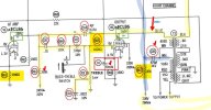
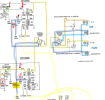
I am now thinking I may have a bad output transformer on the left channel. I tested the voltage on the blue output line on T3 and T2. I have the same low voltage (4.5v) on that T2 line as I see on pin 9 of V5. On T3 it has the correct voltage at about 260v, same as it should be at pin 6 of V6. Attached is a marked up schematic with my voltage measurements in blue.

I hope I am wrong about the output transformer, and that someone here with more experience than me will see something I missed. I appreciate any feedback you may have, good or bad.

Thanks,
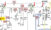
KS400U mu 2023-07-26 150129.jpg KS400U mu1 2023-07-26 150129.jpg
 

Attachments

Register to hide this ad
I'm afraid you/re right... and the transformer will not be easy to come by, as it has a separate feedback winding, plus a hum-bucking tap on the primary. The extra connections are to interleave the primary and secondary windings - this was usually done internal to the transformer, but I've seen several German circuits that connect the winding segments externally. There's a German output transformer on my bench in the basement, but I doubt it's close enough to this one. BTW, the screen grid on the bad channel's ECL86 may be cooked - lose plate voltage and all that current goes to the screen.
 
I'm afraid you/re right... and the transformer will not be easy to come by, as it has a separate feedback winding, plus a hum-bucking tap on the primary. The extra connections are to interleave the primary and secondary windings - this was usually done internal to the transformer, but I've seen several German circuits that connect the winding segments externally. There's a German output transformer on my bench in the basement, but I doubt it's close enough to this one. BTW, the screen grid on the bad channel's ECL86 may be cooked - lose plate voltage and all that current goes to the screen.
Thanks, I'll have to check the tubes again. They both appeared to test good, and both work on right channel.

I was hoping it was not the OT. I know it's not easy to find a replacement. I'll have to give my friend the bad news.
 
I got a bit sidetracked on this project with work travel obligations and then vacation, but am now back in to it.

I confirmed that I had a bad OT on the left channel. I was able to locate and purchase a non-working Grundig SO 220 chassis. Comparing the schematics, they both use the ECL86 tubes and the model for the left OT was very similar (9060-104.03 in the KS400 vs 9060-104.01 on the SO220). It also had a set of tubes and the FM Stereo module included, and was a very fair price.

After some very careful and tedious removal and reconnecting, I now have audio on the Left channel!

I have a couple of observations that I would like to get some input on:

Since I replace the selenium rectifier with a diode bridge, I was expecting I might need a dropping resistor. However, voltage readings are not too far off spec:

  • C1A measures 288v – spec: 290v
  • C1B measures 237v – spec: 230v
  • C1C measures 235v – spec: 225v

I would have expected all to be high, so I am trying to understand why C1A would be slightly low, but well within spec. While C1B and C1C are a bit high as I was expecting. If anyone has some idea about why that would be, I would appreciate the feedback. I think they are all within spec, and would probably leave it, but want to see if this could be a concern.


On V5 I am getting higher than expected voltage on pin 9. I have swapped tubes and it stays the same. Could the C74 capacitor PF4 N150 cause this? I have never seen this type of capacitor and am not sure what would be a good modern replacement to try. Any feedback on this would be appreciated.
  • V5 PIN 6 = 266v – spec: 260v
  • V5 PIN 9 = 123v – spec: 105v
  • V5 PIN 3 = 238v – spec: 230v

  • V6 PIN 6 = 260v – spec: 260v
  • V6 PIN 9 = 103v – spec: 105v
  • V6 PIN 3 = 230v – spec: 230v
 

Attachments

Last edited:
Supply voltages depend on load of various stages, which will vary from unit to unit. I'd say all are close enough.

C74 - 4 pF ceramic is unlikely to be leaky - but you could disconnect either end and see if pin 9 voltage changes. I'd suspect R50 3.9K has gone up in value - would result in higher plate voltage. But it will work fine at 123V if no other problems are found.
 
yeah, 15% tolerance on that stuff is pretty typical. Tube gear generally isn't super fussy about a few volts difference from the schematic values. Drifting resistors mess with this stuff too.
 
This console had side facing electrostatic tweeters. They were not working, so I disassembled them and replaced the foam strip that is a common failure mode for these. They are working now, but I was thinking about upgrading them.

I have been running the stereo on my bench with a pair of 4 ohm 2-way speakers and it sounds great. They are currently attached to the #4, #8 and #6 ground of 7x11 speaker tap on the speaker plug. If the electrostatic tweeters are left out of the circuit, am I getting the full range of the amplifier? Does the Pink / White tap on the OT’s somehow act like a crossover to send all the high frequency to the tweeters?
I guess I don’t understand how that works. It looks like the schematic shows the external speaker plugs switch off the 7x11 speakers when the external speaker plug is in? So, they stop, but the tweeters continue to work?

I have a nice pair of Isophon P915 tweeters that I would like to use. What I wanted to do is replace the electrostatic tweeters with the P915’s. Add a cross over and connect it as a 2-way speaker to the #4, #8 and #6 ground, just like I have now with my bench test speakers.

Will that work? Can anyone explain how the electrostatic circuit works in this stereo? Will I be missing high frequencies if I don't use it?

1693696125568.png
 
Sure looks like the ovals run full range. Any hf roll off is just in the driver.

C85 serves as a "bass blocker" for the electrostatic tweeter. Its getting b+ though so don't just tie a standard tweeter to it. 470pf is too small to deal with a normal impedance tweeter anyway.
 
Yes, my plan is to bypass the current electrostatic tweeter connections completely. It will be just a standard 2way crossover, straight from the current full range tap for the 7x11 speakers. Seems like it should be fine, as that is how it is running on my bench. I just wanted to understand how the taps on the OT work for the electrostatics.
 
I've had a couple of German radios with electrostats, honestly don't remember extra windings or anything for them. Just a resistor off the plate, maybe with a cap across it, and the transformer was just a typical single ended setup.
 
This one has about half of the primary connected to the electrostatic tweeters. Disconnecting them might slightly increase treble output to your external speakers, probably not enough to hear.
 
Back
Top Bottom