• The move to the new server is done. There are some software and database maintenance updates in process. This has us passing the hat around to help out. We appreciate any donations. Seriously, even a dollar helps. The payment page may be found here - https://www.audiokarma.org/support.html

Hafler DH-200 refurb questions

JKent

Active Member
I built a DH-220 back in the day and now regret having sold it (and cheap, too). So I picked up a working DH-200 and plan to do some mild refurb: New electrolytics, new bridge rectifier, inrush current limiter. Bumping up the voltage on the 'lytics and upping C16/17 to 18,000uF 75v.

So far so good but I decided to install some new 5-way binding posts and RCA jacks just to look pretty.

My question concerns R45. I hadn't even noticed it until I removed the RCA jacks. There is one, 2.2 ohm resistor on the right RCA jack only. It connects the green ground wire to the chassis. But there is no resistor on the left side. Shouldn't the left and right channels be the same? Even the original jacks themselves are a little different and this is borne out by the pictorial diagram.

I'm just a hobbyist, so please explain in simple terms ;)

Thanks,
Kent
 
Register to hide this ad
One change is to duplicate the 2.2Ω and run that resistor to a chassis ground and the ground between the caps. Additionally, remove the board out and back to the speaker fuses. Put a jumper in for the out and back and use the speaker fuse on the way to the the output.

I have collected a whole list of upgrades and have worked through a few of them for my pair.

Film caps, film bypass caps, wring changes and all with make the amp better but those Musical Concepts upgrades sure do get a lot of rave reviews.

For the Harry Home Hobbyist the DIYaudio 140 page discussion of the amp has a bunch of changes you can make. Enjoy the storm tonight and get some reading done, make a list and post it. I'll compare it to what I've done/decided to do.

http://www.diyaudio.com/forums/solid-state/31131-hafler-dh-200-220-mods.html
 
Purpose is to break potential ground loop between the 2 channels. I have seen this configuration described in construction articles by Erno Borbely for his Servo 100 and DC100 amplifiers in Audio Amateur magazine circa 1983. It is correct that only one channel has the resistor.
 
Blue,
Thanks. I'm afraid I don't understand some of this.
"duplicate the 2.2Ω and run that resistor to a chassis ground and the ground between the caps." By "duplicate" do you mean put another 2.2 ohm on the left side?
I saw the Musical Concepts pages but I'm not going that route. I just want to refresh these, not spend hundreds of dollars on major design changes. Here's what I've planned so far:
  1. Replace C1 10uF 16V NPE with 10uF 50V Nichicon Muse (or see if I can fit a film cap in there).
  2. Replace C5 470uF 6.3V NPE with 470uF 25v NPE
  3. Replace C10 100uF 80V lytic with 100uF 160V
  4. Replace C16/17 10,000uF 75V 'lytics with 18,000uF 75V
  5. add 47uF (??) bypass caps to 18,000uF caps
  6. New 35 amp bridge rectifier
  7. 16A 0.5 ohm inrush limiter (not sure exactly how to install this)
  8. insulated gold-plated RCA jacks
  9. insulated gold-plated binding posts
  10. replace disc cap on the power switch with an X1/Y2 safety cap
  11. instal PC-6 SEMICONDUCTOR REPAIR KIT from ebay seller Qua-Co Audio (a little pricey at $26 per board but I figure I'll let them match the transistors).
  12. New thermal breakers
  13. Power cord is OK but seems lightweight. Maybe install a heavier gauge?
 
1) either bypass that 10 with a 0.1 film cap or replace with a 5µF poly cap
2) add a 0.1 film bypass cap
3) C7 and C10 are decoupling caps for the Voltage Amplification Stage and Input stage (Replace with 220µF/100V)
7) I used a CL-40, not sure how to fully determine proper ICL but covered current draw of the amp for sure.
9) I hate those clear, cheap plastic dual binding posts and left well enough alone. If I were to replace them, it would be Pomona, Quality, Period.
12) thermal breakers need replacement? Do these age and wear without being triggered?
13) those power cords don't give em confidence, either.

Other recommendations in the doc I have are to move to a star ground instead of the daisy chain ground as built
Previously mentioned jumper for the out and back for the speaker fuse, (jump eyelets 8 and 11) and run eyelet 12 (amp output) through the fuse to the red terminal
Add speaker ground, eyelet 6 to the star ground.

Yes, I added a 2.2Ω resistor to the other RCA jack, both now isolated from the chassis, and ran a wire from that resistor to a screw mounted to the chassis outside the rectifier and ran a line from the screw to the ground buss between the caps. This is three wires to the screw in the hole I drilled in the chassis.

Other items on the list are to install an MOV on the transformer primary, in parallel with an x-cap, 0.47/400. And install another x-cap across the rectifier inputs.
 
Thanks Blue
1) I didn't know 5uF (4.7??) would be OK but will give it a try
3) I had read about increasing the value of those caps as high as 470uF but after I'd placed my Mouser order. May have to place another. So 220?
7) The CL-40 is 6A 5ohm. The one I ordered is CL-101, 16A 0.5 ohm. Is that going to be a problem? And where exactly does it go? (remember--I'm a hobbyist/amateur/slow learner)
9) The new binding posts were just to look pretty. Absolutely no advantage over stock. I had them in my parts box, so....
12) Maybe not. I'll leave them.
13) Yeah--don't know whether to install an IEC or just use a heavier cord.

I've read about the star ground and may give it a try. Have to digest the other grounding and jumper suggestions--may have questions.
Re: x-caps. Does the value matter? I have some .01 and .015 X1 Y2 Safety caps on hand. May need some help finding where to put the MOV. I'll have to look but I think the old bridge rectifier has a disc cap across 2 terminals, so just replace that with an x cap? And again, will .015 do?
 
Last edited:
I put the ICL in one lead of the power cord going into the unit.

I used a CL-90 in a tube preamp with a light bulb power indicator and it has a nice few second rise to full brightness. I just know that is taking the power on surge out of that unit so I can hopefully have many more years with it.

A 16 A unit, that is 3 times the max current draw of the DH-200. Don't know how that will affect the unit since I'm not a electrical parts specifier. But it should slow things down on the way in which is good.

If they are the clear plastic gold binding posts, nope not gonna under any circumstances. Have em on a pair of speakers, unimpressed. But it is your unit.

If you install an IEC get professional advice on whether the ground gets connected and to where. I installed one on a unit (preamp, solid state) and it was a bolt-in replacement. Left the ground not connected because that preamp worked just fine without one and I don't want to build any ground loops and such.

I'l leave the sizing of the x-cap to those that know as well as the MOV, until I study the MOV install.
 
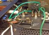
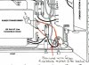
Just to check here. I read on diyAudio that an MOV should go AFTER the fuse, before the switch. I installed the CL101 in that position:
  1. Removed wire running from fuse block eyelet 2 to switch eyelet 3
  2. installed CL101 on a new terminal strip
  3. ran wire from fuse block eyelet 2 to CL101
  4. ran wire from CL101 to switch eyelet 3
Look right?
btw--I found ANOTHER unsoldered connection: The wire from the fuse to the switch. sheesh!

CL101 wiring.jpg Inrush limiter diagram.jpg
 
Last edited:
AK member battradio sold me some matched transistors for my DH 200 last year, a bit less cost than the ebay seller. I've been happy with it after doing similar mods.
 
Kent and inrush limiter and MOV are two completely different devices.
An inrush limiter is a resistor, that starts out at a high resistance limiting
the current, heats up causing it to drop in resistance and let the unit work.
Using an inrush limiter that is too big will cause it not to heat up very much.
I've not spec'd those very often so see what others on DIYaudio are using.
See if Bob Cordell talks about one. It goes in series with the switch or fuse,
etc.
An MOV is an over voltage device and it goes across the line after the fuse
so that it can force the fuse to blow on a surge. There have been articles on
how cheap power strips with MOVs can become fire hazards due, probably,
to poor construction. MOVs degrade with each hit that they take and I forget
the failure mode they either become ineffective or heat up (a lot) and fail.

I would ask people who've done the work on that particular amp and make
sure that you know what you're working with MOV vs. the limiter.
 
Thanks Pete

I do know that MOV & inrush limiter are different--I was just wondering whether the placement would be the same. I recently had an Adcom AC-515 fail to switch the components off and when I opened it I found a toasted MOV. I replaced all 3 MOVs and the relays, too.

As I understand it the DH-500 has an inrush limiter. Maybe I should find a 500 manual. The idea of adding the inrush limiter came from reading several posts on DIYaudio and a listing by ebay seller Qua-Co who seems to have a lot of parts for these amps but I thought the price for a simple inrush limiter was a bit high. That ad states that the inrush limiter should be in series with the switch or primary side of the xformer and mentions that a "rule of thumb" is that if doubling the output capacitance use a 0.5 ohm inrush limiter. I'm going from two 10K caps to two 18K caps so I figured close enough. I just want to be my placement is OK: between the fuse and the power switch, on the hot side of the (now) polarized AC line.
-Kent
 
Here is a thread about inrush limiters:
http://www.diyaudio.com/forums/solid-state/122694-simple-soft-start.html#post1504399

It's been a while since I looked one up, but the detailed data sheet lists a minimum current.
It is required to keep it warm enough. I don't think that is a very good rule of thumb.
I see the CL60 suggested often, but I don't recall the specs and it might be for much bigger
amps.
A simple thing is to measure the primary and secondary DC resistance of the transformer.
If it is fairly high you don't need an inrush limiter.
Do you lights dim when you turn it on?
 
Do you lights dim when you turn it on?
LOL :biggrin: That was a joke, right?
I tested the amp with a cheap pair of speakers when I bought it, just to make sure it worked. Lights were fine.
The CL60 is 5A 10 ohms. The CL101 is 16A 0.5 ohm. I dunno. Just going by the Qua-Co ad. I should have bought from them to get instructions but i was putting together a Mouser order and added it to that.
 
Part of my point was that whoever is selling them on ebay doesn't know what
they are doing if they are suggesting a .5 ohm unit, it will do nothing having
such a low resistance. But on the other hand that amp probably doesn't need
one so ebay seller makes some money and you feel good because you put one
in your amp.
Look up the min and max current for the CL60 and I'll take a look at the numbers.
 
CL-60 is 10Ω/5A.

I used CL-40, 5Ω/6A for my DH-200s.

Used the CL-90 in some tube gear, 120Ω/2A, gives a nice slow brightness increase on the power indicator bulb. Unit has a 0.5A slo-blow fuse so that 2A ICL should be fine and it will drop the voltage just a bit, too, leaving 1.55Ω in the circuit at 25% load.
 
OK, still working on the inrush limiter question but here's another Q:
I replaced the 10,000uF power supply caps with 18.000uF. I see that some recommended bypass caps. I used the popular Vishay MKP1837 0.01uF caps on all of the electrolytics on the PC boards but what value should I use on these big suckers? I have 2 shoeboxes full of caps so I'd like to use something I have on hand. I've seen anything from 0.01uF to 10% (that would be 1800uF!!).
While Googling “power supply bypass caps” I came across a Quad amp mod where the original 10,000uF power caps were replaced with 22,000uF caps. Those were then bypassed with a 0.22uF polypro, a 0.033uF PIO, a little polystyrene and a little silver mica. I have some Russian PIO and silver mica caps, and of course a bunch of polypro and mylar caps so I could cascade a few of those but it sounds like the total capacitance is minuscule. Does this really make a difference?
What do you guys recommend?
 
Last edited:
OK, still working on the inrush limiter question but here's another Q:
I replaced the 10,000uF power supply caps with 18.000uF. I see that some recommended bypass caps. I used the popular Vishay MKP1837 0.01uF caps on all of the electrolytics on the PC boards but what value should I use on these big suckers? I have 2 shoeboxes full of caps so I'd like to use something I have on hand. I've seen anything from 0.01uF to 10% (that would be 1800uF!!).
While Googling “power supply bypass caps” I came across a Quad amp mod where the original 10,000uF power caps were replaced with 22,000uF caps. Those were then bypassed with a 0.22uF polypro, a 0.033uF PIO, a little polystyrene and a little silver mica. I have some Russian PIO and silver mica caps, and of course a bunch of polypro and mylar caps so I could cascade a few of those but it sounds like the total capacitance is minuscule. Does this really make a difference?
What do you guys recommend?

The laws of diminishing returns is kicking, here, IME. At some point, raising the capacitance only prolongs the power down time to drain them off. As for the stacked bypass caps, again, the laws of diminishing returns kicks in even faster. Bypassing caps was a fun thing in the late 80s and 90s and everybody did it back then. I'm not sure you'll hear the effects of continuing to stack bypass caps at all - or even the first one if you're using more modern caps. The materials in capacitors has improved far more than using old techniques; some of which were spotty in their results anyway.

Focus on rebuilding the DH-200 and then re-evaluate whether you think they're needed. It is easy to add them later.

Cheers,

David
 
CL-40 looks about right.
Kent, upping those 10,000 uF's in the PSU helps to tighten up the bass
especially when pushed and into 4 ohms.

Leach on PSUs:
https://leachlegacy.ece.gatech.edu/lowtim/pwrsply.html

I would do your basic mods, clean up all soldering etc. USE IT.
Make sure that it is working fine and biases up properly.
Then later add bypass caps as you view they are needed, I don't believe
that they are.
 
Last edited:
Back
Top Bottom