


KingWzrd
New Member
Hello everyone, I have a DH-500 that recently had the right channel stop putting out sound. I've read a few posts about ensuring the relay clicks when the amp it switched on (it does) and all fuses inside and the back are not blown. The light is normal on the front of the unit and the fan is spinning like usual.
I've read the manual that states, "If the relay will not close (no signal at the output, with an input signal) check for excessive DC offset (over 1.8 volts) from either channel at locations 7 or 8 on PC-9-the small relay circuit board. This indicates a defective amplifier channel, requiring competent service. If there is no indication of excessive offset, the fault is in the relay or
on the PC-9 circuit board."
For fun, I checked the voltage at positioms 7 and 8 on the PC-9, and they were -.7mV and 332mV. I don't really know what these values indicate but they are within the range stated in the manual and the relay closed, so this leads me to believe its not the PC9 or the relay.
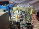
In the photo. You can see there is a burn spot under the sand resistor, but there is the same burn on the other channel as well. I made sure the solder connection was good and it seems to be.
Edit** I just found this posting, and my problem appears similar to them: https://audiokarma.org/forums/index.php?threads/hafler-dh-500-channel-out-help.117548
How should I go about testing each component of the amp board? Do I unsolder all the wires on the left and right to remove it from the amplifier entirely before testing components? Or do I test them while hooked inside the amp?
Thank you for your time and help!
I've read the manual that states, "If the relay will not close (no signal at the output, with an input signal) check for excessive DC offset (over 1.8 volts) from either channel at locations 7 or 8 on PC-9-the small relay circuit board. This indicates a defective amplifier channel, requiring competent service. If there is no indication of excessive offset, the fault is in the relay or
on the PC-9 circuit board."
For fun, I checked the voltage at positioms 7 and 8 on the PC-9, and they were -.7mV and 332mV. I don't really know what these values indicate but they are within the range stated in the manual and the relay closed, so this leads me to believe its not the PC9 or the relay.
In the photo. You can see there is a burn spot under the sand resistor, but there is the same burn on the other channel as well. I made sure the solder connection was good and it seems to be.
Edit** I just found this posting, and my problem appears similar to them: https://audiokarma.org/forums/index.php?threads/hafler-dh-500-channel-out-help.117548
How should I go about testing each component of the amp board? Do I unsolder all the wires on the left and right to remove it from the amplifier entirely before testing components? Or do I test them while hooked inside the amp?
Thank you for your time and help!
Attachments
Last edited:


