troutmaskrep
New Member
I’m working on restoring a Harman Kardon 330a amplifier that was blowing fuses due to multiple shorted transistors. Among other issues, one of the four CDC8002/9002 “flying saucer” transistors was blown. Following advice from an old thread on a different amplifier model, I replaced all four with BC639 and BC640 transistors.
When I turned the amp on with speakers connected, I only heard noise and distortion out of both channels. To troubleshoot, I reinstalled two of the original (still-working) “flying saucer” transistors in one channel, because I had also replaced the output transistors (one of which was blown) and needed to confirm where the fault lay. The channel with the original “flying saucers” now works fine, so I know the issue lies in the other channel with the BC639/BC640 transistors.
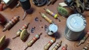
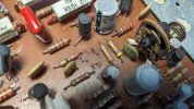
I’ve verified the pinouts multiple times using a multi-function transistor tester, and I carefully bent the legs to match the original CDC8002/CDC9002 layout. Still, there is noise and distortion in the channel using the BC639/BC640 pair.
My question is: Could this be a bad transistor substitution for this particular circuit, or is there something else I might be missing? I'm particularly keen to understand why this particular substitution does not work in this circuit, and how I might identify a substitution that will work.
Also, I didn't try to do any matching on the PNP/NPN pairs since a) I don't have the right test equipment and b) the hfe for the BC639/BC640 using my multi-function tester was so wildly different I knew I could not use that method to perform matching.
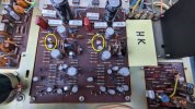
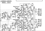
The transistors in question are TR507/TR508 and TR607/TR608.
Another note: Both channels were clear with the transistor substitutes if i kept the volume extremely low - my theory is this is the 'class A' region where the NPN/PNP pairs don't need to complement each other
When I turned the amp on with speakers connected, I only heard noise and distortion out of both channels. To troubleshoot, I reinstalled two of the original (still-working) “flying saucer” transistors in one channel, because I had also replaced the output transistors (one of which was blown) and needed to confirm where the fault lay. The channel with the original “flying saucers” now works fine, so I know the issue lies in the other channel with the BC639/BC640 transistors.
I’ve verified the pinouts multiple times using a multi-function transistor tester, and I carefully bent the legs to match the original CDC8002/CDC9002 layout. Still, there is noise and distortion in the channel using the BC639/BC640 pair.
My question is: Could this be a bad transistor substitution for this particular circuit, or is there something else I might be missing? I'm particularly keen to understand why this particular substitution does not work in this circuit, and how I might identify a substitution that will work.
Also, I didn't try to do any matching on the PNP/NPN pairs since a) I don't have the right test equipment and b) the hfe for the BC639/BC640 using my multi-function tester was so wildly different I knew I could not use that method to perform matching.
The transistors in question are TR507/TR508 and TR607/TR608.
Another note: Both channels were clear with the transistor substitutes if i kept the volume extremely low - my theory is this is the 'class A' region where the NPN/PNP pairs don't need to complement each other
Attachments
Last edited: