CalvinBeck
Member
 Long time lurker, first time poster. First let me say I am continually impressed by the helpfulness and free exchange of knowledge I have seen on Audiokarma. I've only been working on electronics as a hobby for three years. I went through that "know enough to be dangerous" phase, moved on to shotgunning, but things have been starting to click lately. I'm pretty shy about posting anything publicly. I don't use social media. So this is hard for me to do, but after a week of being stumped, I decided it's time to start participating and ask the community for help.
I have a Harman Kardon 330C that I acquired for a slightly inflated price from the auction site. When it arrived I was pleasantly surprised at its condition. It's beautiful, barely a scratch on it. The controls were dirty (dang tape monitor). Other than that, it worked. Clean sine wave, great square wave, negligible dc offset, barely had to adjust the bias. It put out nearly 30 watts. All of the voltages on the pinouts of the power board looked good, with the exception of two which were about a volt and a half low. Where +B2 and -B2 are on this machine, I have no idea, so I couldn't check those.
So why not leave well enough alone and just enjoy the thing? I suspect there would be fewer of us that do this as a hobby if we could answer that question.
There were a few slightly bulging caps and considering they're all 45 years old, I decided to replace them. I did the power board, tone board, am/fm board. Tested on the dimbulb and listened after each board. Everything seemed fine. Then I decided to get a little radical and change the diodes on the power board. Why, I have no idea. I should mention, the filter caps hold voltage for a long time. C3 will hold -6.5V for over a day and C4 will hold 0.5V. Knowing this, I bled the voltage down to 1mV with a 1k resistor. I installed the four diodes D4, D5, D601, and D602 with UF 4003-E3/73s. The next day, to my horror, I discovered that I had installed D4 and D5 backwards, and C3 had gone back up to -6.5V. I don't know if this voltage went somewhere it shouldn't have, but after putting them back the right way and testing the voltages I found that I had no voltage on LP11, which is tied to the collector of Q601.
I've gone on long enough. Suffice it to say I don't know if my diode mistake is a coincidence, since the diodes I reversed appear to be connected to a separate circuit with its own rectification and filtering, than the ones on the high voltage rails.
If anyone can explain to me where Q601 gets its Vcc and where that voltage/current could be, I'd really appreciate it.
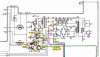
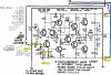
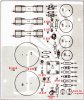
I have attached three diagrams of voltages I have measured.
Last edited: