Hello all! I have had a Harman Kardon 430 for a few years but recently have completely lost all sound. When I power it up, all the lights turn on and even the dial and stereo lights are active when moving through FM. However I'm not getting any sound through speakers or from headphones. I have a multimeter but I'm not really sure what to check. I have read that there should be a click a few seconds after powering it on but I don't hear a click, though I don't know that I ever noticed one before when it was working. I have also replaced some fuses that appeared to be blown.


You are using an out of date browser. It may not display this or other websites correctly.
You should upgrade or use an alternative browser.
You should upgrade or use an alternative browser.
Harman Kardon 430 powers up but no sound
- Thread starter keyonce
- Start date
-
- Tags
- harman kardon 430
Register to hide this ad

cademan
Lunatic Member
Welcome!
Do you wish to work on it yourself because you are going to need some electronics background if you do. Otherwise you will need to take it to someone else.
Some HK stuff don't use speaker protection relays. You can look inside and take some pics and I or someone else here can point it out if it has one.
Question: Did the new fuses blow also? Were the old blown fuses blackened?
Do you wish to work on it yourself because you are going to need some electronics background if you do. Otherwise you will need to take it to someone else.
Some HK stuff don't use speaker protection relays. You can look inside and take some pics and I or someone else here can point it out if it has one.
Question: Did the new fuses blow also? Were the old blown fuses blackened?
Thank you! I’d very much like to repair this myself if possible. The new fuses did not blow after installed and I turned on the unit. I don’t recall if the ones I replaced were blackened and unfortunately they’re in the trash now.
I’ve taken some pictures and hope these are useful.

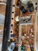
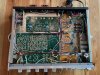

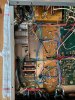
I’ve taken some pictures and hope these are useful.

Interesting. It looks like someone replaced the main filter caps but nothing else.
That particular receiver doesn't have a relay, so you won't hear a "click" ever. Did you check the rear speaker fuses along with the others?
Thanks for the advice. I took a closer look at all of the fuses with a multimeter and now see that both the speaker fuses are blown as well as one inside the chassis. The one inside is clearly labelled "3A - 250V" and I have one to replace it.
However, the speaker ones I'm less sure about. The label on the receiver and in the service manual say "3A 3AG". The fuses themselves are clearly different and one is labelled "32V 3A" while the other is labelled "3A 250V". Would it make sense to use "3A 250V" in both? The one labelled 32V is clearly popped and the one labelled 250V is physically longer and looks OK on inspection but with multimeter indicates no continuity.
After a little research I just stuck the 3A 250V fuses I have and fired it up and I have sound again! Thanks for all the help on this.
Though now I have another problem, the left channel always has some crackling/humming/white noise. It doesn't matter the input or if adjusting any knobs, it's always there. It's most noticeable when nothing is playing at all (left side has white noise and right side is silent). If I'm moving around the knobs I can hear a little in the right but I'm not so worried about this. Based on other posts it seems like I probably have a problem with some capacitors. Any tips or where to focus or should I re-cap specific boards?
Though now I have another problem, the left channel always has some crackling/humming/white noise. It doesn't matter the input or if adjusting any knobs, it's always there. It's most noticeable when nothing is playing at all (left side has white noise and right side is silent). If I'm moving around the knobs I can hear a little in the right but I'm not so worried about this. Based on other posts it seems like I probably have a problem with some capacitors. Any tips or where to focus or should I re-cap specific boards?
The crackling noise you describe sounds like a bad transistor, could be the differential pair on the amp board.
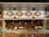
Thanks! Could you help guide me a bit more? I'm not really sure what to look for and what to replace. Based on your comment, I found in the service manual Q401,402,403,404 refer to "2SC1345(F) Differential Amp". Is this what you were suggesting? I found them on my receiver and attached a picture with them circled.
Or were you referring to the things labelled "2SC1030" in the second attached image?
In either case, would someone be able to help me find appropriate replacement parts and maybe some information about replacing them? I've found lots of good resources about replacing capacitors but not so much about other components.

buttahman
Active Member
The ones you have circled{Q401,403} in the first pic are the differential transistors for one channel, Q402 and Q404 would be for the other channel. Would probably be a good idea to test the voltages on those transistors first using your meter; use a grabber attachment on the end of your probe instead of trying to measure the legs by holding it steady. If you haven't already check out vinylengine.com and you'll be able to download the service manual for this receiver for free. I believe the replacement for those transistors is KSC1845, hopefully someone can confirm that.
The 2sc1030 devices in the second picture are your output transistors.
The 2sc1030 devices in the second picture are your output transistors.

Soundork
Super Member
It looks like there is an active device such as, transistor in your power amp that is malfunctioning. There is a small chance that you can find it by poking at it. Grab a rod made from insulating material such as pencil or a wooden skewer and poke at those transistors. Another method is to freeze them one by one.
KSC1845 is one possible replacement as buttahman noted. MPS18 and BC550C are another. There are two parameters that you should watch out the most for if you want to do research on your own: hfe of the low powered transistors for this particular receiver - it must be above 500 (you can go little lower, like 450) and leg orientation. I wouldn't worry about the latter, but you have to be careful with your installation...if the leg order isnt the same as that in the original transistor, you will need to bend legs in order to place them in the proper holes.
Soundork
KSC1845 is one possible replacement as buttahman noted. MPS18 and BC550C are another. There are two parameters that you should watch out the most for if you want to do research on your own: hfe of the low powered transistors for this particular receiver - it must be above 500 (you can go little lower, like 450) and leg orientation. I wouldn't worry about the latter, but you have to be careful with your installation...if the leg order isnt the same as that in the original transistor, you will need to bend legs in order to place them in the proper holes.
Soundork
I have a grabber attachment for my multimeter on order. Until then can you explain what I’m looking for by poking these transistors?
Also is this the part I should order? I’m guessing I should go ahead and replace all 4 so they match?
https://www.mouser.com/ProductDetai...rchild/KSC1845FTA?qs=UMEuL5FsraDCmxWozTypUA==
Also is this the part I should order? I’m guessing I should go ahead and replace all 4 so they match?
https://www.mouser.com/ProductDetai...rchild/KSC1845FTA?qs=UMEuL5FsraDCmxWozTypUA==
Soundork
Super Member
I think you should first find the problem, before throwing parts at it in hope that it would get fixed.
When you poke at components you might be able to intensify the symptoms. Not very effective, but it is worth trying. Also, did you clean the controls? You should although, this is not very likely to be the problem, since you reported that it is independent of the volume.
So, clean the controls i.e. switches and potentiometers first. Poke at everything you see on the amp board transistors, resistors, potentiometers, etc. until you have a fully functioning multitester and start testing. Also poke those big capacitors in the PS.
I am not exactly sure if this transistor would work as its hfe parameter is rated from 300 to 600. You might receive anything in between. this one is marked as KSC1845F, the direct replacement is KSC1845U, which is rare to find. I think some people have successfully used KSC1845F, but I cannot guarantee it would work. Let's not change parts for now and try to isolate the problem first.
Soundork
When you poke at components you might be able to intensify the symptoms. Not very effective, but it is worth trying. Also, did you clean the controls? You should although, this is not very likely to be the problem, since you reported that it is independent of the volume.
So, clean the controls i.e. switches and potentiometers first. Poke at everything you see on the amp board transistors, resistors, potentiometers, etc. until you have a fully functioning multitester and start testing. Also poke those big capacitors in the PS.
I am not exactly sure if this transistor would work as its hfe parameter is rated from 300 to 600. You might receive anything in between. this one is marked as KSC1845F, the direct replacement is KSC1845U, which is rare to find. I think some people have successfully used KSC1845F, but I cannot guarantee it would work. Let's not change parts for now and try to isolate the problem first.
Soundork
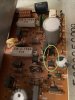
Wow that was fun! I just tried the poke test and I think I found the problem. Picture is attached but when I poked at one of the transistors that we were focusing on (Q404) the left channel completely went out and I heard no music, no crackling, but a hum. After a few seconds crackling and sound would return (a little worse at first but then settling back to the standard amount of white noise I've been hearing). I can re-poke and get it to happen every time. Nothing else I poked had any impact but I did notice one capacitor was a little loose compared to others (poking it had no audible impact).
Does this mean possibly a solder joint that is faltering or do I need to replace this component. If the latter, it seems like a challenge to find a suitable replacement.
First photo is the transistor that when poked cuts out left channel and second is of the capacitor that is loose.
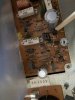
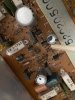
Does this mean possibly a solder joint that is faltering or do I need to replace this component. If the latter, it seems like a challenge to find a suitable replacement.
First photo is the transistor that when poked cuts out left channel and second is of the capacitor that is loose.

captouch
Addicted Member
Look on the solder (other) side and see how the solder points look for those two components. If they don’t appear solid under magnification (maybe cold solder joints after so many years), you can retouch them to reflow them (and add a bit more solder if needed) and see if the problem persists - of course with the unit powered off.
And if it turns out it’s cold/flaky solder joints, there’s a good chance there are others not far behind and you can visually inspect all the other points and touch up those that don’t look rock solid.
On a receiver that age, you’ll probably eventually want to replace the electrolytic caps. Some wait for failure before doing so, some proactively do it before anything fails.
But you definitely want to fix the problem first before recapping/restoring (if you go that way) to avoid potentially adding more issues and not knowing what caused them.
And if it turns out it’s cold/flaky solder joints, there’s a good chance there are others not far behind and you can visually inspect all the other points and touch up those that don’t look rock solid.
On a receiver that age, you’ll probably eventually want to replace the electrolytic caps. Some wait for failure before doing so, some proactively do it before anything fails.
But you definitely want to fix the problem first before recapping/restoring (if you go that way) to avoid potentially adding more issues and not knowing what caused them.
Hmm, I'm not really sure what I'm looking for on these solder joints but they seem pretty solid to me. I can't seem to find any suitable replacements and the closest available is the KSC1845FTA. I've seen reports on other threads of these being used successfully on HK430s so I think I'll give this a try unless there are other suggestions.
Soundork
Super Member
Even if they look solid, it doesn't mean they are. You got a very good advice from captouch: retouch. What this pretty much means is, go with the soldering iron and redo the solder joint, so the solder sticks up to the leg again. You need to heat up both leg and solder. Melting the solder isnt enough. Place a heat sink on the leg you are working on. Place it towards the top, where it ends and the plastic starts.Hmm, I'm not really sure what I'm looking for on these solder joints but they seem pretty solid to me. I can't seem to find any suitable replacements and the closest available is the KSC1845FTA. I've seen reports on other threads of these being used successfully on HK430s so I think I'll give this a try unless there are other suggestions.
This is what heat sink looks like. If you dont have one, improvise.
https://www.amazon.com/H-2SL-Goot-H...t=&hvlocphy=9003181&hvtargid=pla-441407903450
You can try the F, but I also gave you other, better transistor options. They would work, but you have to adjust their orientation i.e. make sure the correct leg goes into the correct hole.
OK I can do this first. I don’t have this heat sink but I can order one. Just to make sure that this should be attached to the leg on the top of the board and the retouch the solder on the back? Would it be necessary to desolder and resolder or apply any extra solder?
Finally is this one you suggested instead if this doesn’t work? I’ll just need to figure out how to orient the legs because it is different from the stock one?
https://www.mouser.com/ProductDetai...T5ggMwA1pEqzIsZBZyIR0pWn3QUf2SAoaAo-tEALw_wcB
Finally is this one you suggested instead if this doesn’t work? I’ll just need to figure out how to orient the legs because it is different from the stock one?
https://www.mouser.com/ProductDetai...T5ggMwA1pEqzIsZBZyIR0pWn3QUf2SAoaAo-tEALw_wcB
Soundork
Super Member
Lets see first if resoldering the joints would fix the problem and then we can look for new parts if necessary.
The best method would be to remove the old solder and apply new one. Do you have a desoldering tool? It looks like this:
https://www.amazon.com/WEmake-WM-SP...t=&hvlocphy=9003181&hvtargid=pla-491294181333
For a few dollars more you can get an electric one, that's what I have.
Assuming that you do not have one, just place your iron tip along the leg at the bottom side of the board, where it comes out. The solder would start to melt and eventually you would touch the leg with the iron tip. You need to stay there about a second. It is better if you had the heat sink, but you could improvise, get a buddy touch the leg close to the plastic part while you are performing this. You can use any metal object, screwdriver, fork handle ect. This will take part of the heat that travels up along the leg to the transistor. Someone with a lot of soldering experience does not have to do that, but for your own sake and for the sake of the part you are better off with it. Oh, and you might need to add some new solder if necessary
If you have the desoldering iron, melt the solder around the leg you are working on, but do not touch the actual leg and suck the old solder out with the tool, then apply flux and new solder.
The best method would be to remove the old solder and apply new one. Do you have a desoldering tool? It looks like this:
https://www.amazon.com/WEmake-WM-SP...t=&hvlocphy=9003181&hvtargid=pla-491294181333
For a few dollars more you can get an electric one, that's what I have.
Assuming that you do not have one, just place your iron tip along the leg at the bottom side of the board, where it comes out. The solder would start to melt and eventually you would touch the leg with the iron tip. You need to stay there about a second. It is better if you had the heat sink, but you could improvise, get a buddy touch the leg close to the plastic part while you are performing this. You can use any metal object, screwdriver, fork handle ect. This will take part of the heat that travels up along the leg to the transistor. Someone with a lot of soldering experience does not have to do that, but for your own sake and for the sake of the part you are better off with it. Oh, and you might need to add some new solder if necessary
If you have the desoldering iron, melt the solder around the leg you are working on, but do not touch the actual leg and suck the old solder out with the tool, then apply flux and new solder.
captouch
Addicted Member
Hmm, I'm not really sure what I'm looking for on these solder joints but they seem pretty solid to me. I can't seem to find any suitable replacements and the closest available is the KSC1845FTA. I've seen reports on other threads of these being used successfully on HK430s so I think I'll give this a try unless there are other suggestions.
You really need to look with good light and under magnification, esp if you're older like me! But the fact that the capacitor seems "loose" says that something is happening there, whether that's a instable solder connection or a corroded leg on that cap. If you can keep a finger on the cap and wiggle it while you're looking at the solder side, you may see one of the legs below moving.
Place a heat sink on the leg you are working on. Place it towards the top, where it ends and the plastic starts.
This is what heat sink looks like. If you dont have one, improvise.
https://www.amazon.com/H-2SL-Goot-H...t=&hvlocphy=9003181&hvtargid=pla-441407903450
You can try the F, but I also gave you other, better transistor options. They would work, but you have to adjust their orientation i.e. make sure the correct leg goes into the correct hole.
That's cool, I don't own a heat sink, but I have worried about overheating components. This looks like a great staple of a hobbyist's toolbox.
OK I can do this first. I don’t have this heat sink but I can order one. Just to make sure that this should be attached to the leg on the top of the board and the retouch the solder on the back? Would it be necessary to desolder and resolder or apply any extra solder?
Finally is this one you suggested instead if this doesn’t work? I’ll just need to figure out how to orient the legs because it is different from the stock one?
https://www.mouser.com/ProductDetail/Central-Semiconductor/MPSA18-PBFREE?qs=u16ybLDytRZgZ5NNQU6fnQ==&mgh=1&gclid=Cj0KCQjwmIuDBhDXARIsAFITC_6BtKsHLE3hNSAiGHVg1NZT5ggMwA1pEqzIsZBZyIR0pWn3QUf2SAoaAo-tEALw_wcB
Yes, apply the heat sink to the legs at the top. It'll absorb heat and prevent most of it from getting to the component itself. It's a good idea, but it also depends on your soldering technique. If you're quick enough and you're dealing with a cap or transistor that you might replace soon enough anyway (and don't want to wait for the heat sink to arrive), I wouldn't say it's strictly necessary. But if you're the type that lingers in your soldering, which isn't uncommon for people newer, it's definitely a good idea. But it's never a good idea to linger very long anyway if you can help it, even with a heat sink, because you can lift a solder pad from the board if heat is applied for too long.
As far as desoldering, not really necessary. If there's a fair amount of solder there, you can just touch it up. if there's not much there to reheat, you can add a bit more. Of course, it never hurts to just heat the connection suck up the old solder if there's any doubt. Sometimes the old solder just looks bad/different, in which case, it probably would be good to just suck up the old solder and add new.
The transistor terminals (E, C, B) are labelled on the PCB, but it's always best to verify because sometimes the PCB labels are wrong (whether it's polarity of a capacitor or transistor terminals) - don't always trust the PCB labels. You can look for the old transistor P/N, find a datasheet, and verify the order of the legs and that it matches the PCB labeling. Then look at the leg order/ID of the new transistor, and make sure they go to the right place. Sometimes, you'll have to swing/bend a leg across the other legs in order to get it to the right place. If there's any chance of contact between legs, it's a good idea to put some heat shrink or wire insulation on the leg that's bending across the others to insulate it from possible contact.
When you strip a wire, you get bits of wire insulation with no wire inside. I typically keep some of those around to use as insulators in such cases - just cut to required length. Saves you from having to use really narrow heat shrink.