• The move to the new server is done. There are some software and database maintenance updates in process. This has us passing the hat around to help out. We appreciate any donations. Seriously, even a dollar helps. The payment page may be found here - https://www.audiokarma.org/support.html

Harman Kardon 730 Left Channel Bias

Zeus12

Active Member
Greetings Audiophiles, :)

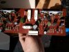
Started the recap/restoration of the HK 730. Those little popping/cracking sounds were getting on my nerves.

I started with the Power Amp PC Board and so far I have replaced all electrolytics on the board with Nichicon UKL Series, and the Q401-406 with KSC1845 (F) -- all according to @dlucy wonderful restoration.
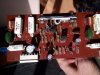
HK 730 - Power Amp Left Channel.jpg
Right Channel:
HK 730 - Power Amp Right Channel.jpg

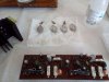
Also cleaned the pin contacts and put new thermal compound (Dow 340) for the output transistors:
HK 730 - Power Amp Output Transistors.jpg

Power Amp NEC Output Transistors
HK 730 - Power Amp Board Pins.jpg

I have an issue with the BIAS on the Left channel (VR01). I can only get it to around 14mv. The right channel is Biasing OK. Yes, I know I should have replaced those flaky trimpots. Inventory mistake.

I left both channel at around 14mV then and have been listening to it for a couple of hours now and NO MORE POPPING SOUNDS!!!!:banana::banana::banana::banana: So those original 2Sc1400´s were the culprit!! Thanks again to @dlucy explanation:

the 2SC1400 diff amp small signal transistors on the power amp boards have “gone noisy” in the second hk730 I’m working on. They are producing very loud crackling that begins at startup, occurs randomly, not tied to control knob adjustment, not specific to any function selection, and unaffected by volume control.
replacing them with hfe-matched KSC1845F eliminated the crackling, so these 2SC1400 were noisy.


It looks to me like that VR01 is the culprit (the metal part looks way too bent compared to the other one) so I will order 2 new trimpots from Mouser. Can I use it in the meantime? Should I change the BIAS on the other channel to the original specs (35mv+-5) or leave them both at around 14mv where they are now?

Cheers!!:beerchug:
 
Register to hide this ad
Greetings again fellow audiophiles!!

Just realized that I didn´t connect the 8 Ohm (50W) resistors across the speaker terminals. According to the directions, BIAS adjustment is as follows:
HK 730 Bias Checking.jpg

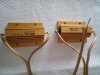
Did just that but IT MAKES NO DIFFERENCE in the measurements. I did notice that when I had it on FM and cranked up the volume, the DMM went from 14mv into the 40-60 mVs. The resistors I used were these, thanks to @JJCalvillo for showing me how to connect them:
8 ohm 100W resistors.jpg

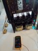
So I connected these and took the BIAS as follows:

HK 730 - BIAS Adjustment.jpg

Don´t know if I´m doing something wrong here.:idea: So far it has been running GREAT. Heatsink is a lot cooler to the touch than before. I´m sure that old thermal compound paste wasn´t doing it´s job. AND NO POPPING NOISES :banana::banana::banana::banana:

Another thing to mention is that most of the caps measured within specs - C407,408 were PERFECT. The smaller caps (C401,402) were about 20% over but I think that should be within tolerance, from what I have seen. Love the sound!!

Cheers!!!:beerchug:
 
I had a problem with bias on one channel when I was working on my 730. I had recapped the amp board but left transistors alone. I replaced the crummy trimmers and was then able to bias both sides w/o any problem.

I used these, but it looks like Mouser is waiting a long while for them now, and Digikey sells in multiples of 200. https://www.mouser.com/c/?q=652-3362W-1-102
You could look for a trimmer with a different number of turns. Or a trimmer with a different foot/trim screw set up and modify it to fit.
 
:rflmao::rflmao: You´re absolutely right!! Looks like it´s December 5th and not May 12th. European system is
day/month/year whereas U.S. system is month/day/year. Great catch!!
 
Greetings fellow audiophiles,

While waiting for the trimpots, I decided to do the Tone board. I´m still getting an occasion little "pop" -- nothing compared to before doing the Main amp board, but still comes up once in a blue moon.

Started with the transistors and instead of the 2SC1345´s, which is what I see everybody has, I had these:
HK 730 - Tone Board Q503-Q508.jpg

I used the KSC1845´s for a replacement and for Q501,Q502 the KSA992. Anybody knows why my unit had the
2SC1775 in there instead? Did I use the right replacement for it?


For the caps, I only changed the two 1.5uf´s with WIMAs and C503,C515 with UKLs.
HK 730 - Tone Board replaced parts.jpg

From what I have seen so far, my unit must have been VERY WELL TAKEN CARE OF because all the caps I have measured were well within specs:
HK 730 - Tone Board C503 Original Cap.jpg

Even those 2 little blue 1.5uf caps measured great. Put WIMAS in there as a replacement--love that red color they got.:rflmao::rflmao:
HK 730 - Tone Board 1.5uf original cap.jpg
HK 730 - Tone Board WIMAS replacements.jpg

Decided to give it a listen and continue with the recap later. I´m very proud of myself that I didn´t lift any traces this time and got the soldering almost perfect. Wanted to tackle those "trannies" first since most likely, from what I have read, the popping sound is a big tale tale sign of a bad transistor. So far, IT´S WORKING GREAT!!!!!!!!
I think this has eliminated the last remnants of those little pesky "pops" that mess up your groove. :banana::banana::banana::banana::banana::banana::banana::banana::banana::banana::banana::banana::banana::banana::banana::banana::banana::banana::banana::banana:

Big thanks again to "el maestro" in HKs @dlucy and rest of the nice people on this forum. In the meantime, I will continue enjoying this beauty and it has SOMETHING SPECIAL that makes you want to listen. Can´t express it but I know that this one is A KEEPER!!! ABSOLUTELY NO FATIGUE!! Love it!!!

Cheers!!!
 
2SC1345 and 2SC1775 are common factory substitutes in these units… and KSC1845 are fine replacements for them. That’s what I use.
 
:bowdown::bowdown::bowdown::bowdown::bowdown::bowdown::bowdown:Wow!!! Got a reply from the teacher himself!!! Big thanks @dlucy .
Love your attention to detail and I don´t think you have OCD. You are just a "perfectionist"...:rflmao::rflmao::rflmao:

"Today I want to be better than yesterday and tomorrow I want to be better than today."
 
Greetings again!

The "Mode/Control Switch B PC Board" has 2 caps and 4 transistors. Could someone please enlighten me on what these components do?
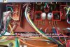
HK 730 - Control Board B.jpg

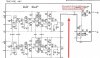
Are the transistors Q509,510 (2SC1345(E)) and Q511,Q512 (2SA836(E)) in the signal path at all times? Are they called differential pairs--they are back to back, so that´s a sign. Or, are they complimentary pairs? I see on is NPN and the other is PNP. They work together from what I see. And most importantly, how come they are not in the "Schematic Diagram"?:idea:

HK 730 - Tone Board Diagram Schematic.jpg

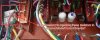
I know it´s a pain to get those 2 Mode/Control Boards out. Apart from removing the headset jack (phone) is it necessary to desolder anything? For example, those 2 resistors in the corner? I am getting the sweats just by thinking that I might mess up one of those wires.
HK 730 - Control Board B Resistors.jpg

I have had the amp on now since yesterday and I think I have heard one little "hiccup" from it. I am not sure if it´s the amp or perhaps, source related. Maybe I AM PARANOID about "popping" sounds now and I might be SUPER SENSITIVE to it. Maybe my brain is "LOOKING" for it? :music::music:

Cheers!!
 
Greetings again!

The "Mode/Control Switch B PC Board" has 2 caps and 4 transistors. Could someone please enlighten me on what these components do?
View attachment 2559303

Are the transistors Q509,510 (2SC1345(E)) and Q511,Q512 (2SA836(E)) in the signal path at all times? Are they called differential pairs--they are back to back, so that´s a sign. Or, are they complimentary pairs? I see on is NPN and the other is PNP. They work together from what I see. And most importantly, how come they are not in the "Schematic Diagram"?:idea:

View attachment 2559313

I know it´s a pain to get those 2 Mode/Control Boards out. Apart from removing the headset jack (phone) is it necessary to desolder anything? For example, those 2 resistors in the corner? I am getting the sweats just by thinking that I might mess up one of those wires.
View attachment 2559318

I have had the amp on now since yesterday and I think I have heard one little "hiccup" from it. I am not sure if it´s the amp or perhaps, source related. Maybe I AM PARANOID about "popping" sounds now and I might be SUPER SENSITIVE to it. Maybe my brain is "LOOKING" for it? :music::music:

Cheers!!
There are 3 wires that come through the board that are soldered to the top pins of a switch. Green, Pink (or purple), and Black. You cannot separate the boards without desoldering them.
 
Hi @Skywatcher

Thanks for enlightening me! :):)

The main amp board is SO EASY to take out but those little Mode Boards are a real pain in the behind--especially for a rookie like me.

Those 2SC1345´s (Q509,510) are on the "list" and should be definitely changed. Are they "engaged" or in the signal path at all times? or only when one of the switches is turned on?

Cheers!!!
 
Hi @Skywatcher

Thanks for enlightening me! :):)

The main amp board is SO EASY to take out but those little Mode Boards are a real pain in the behind--especially for a rookie like me.

Those 2SC1345´s (Q509,510) are on the "list" and should be definitely changed. Are they "engaged" or in the signal path at all times? or only when one of the switches is turned on?

Cheers!!!
Scroll down further in the manual to page 21/22. It shows them and they are in the filter circuit. Yes they are in the signal path.
 
While you're in there, I'd put some nice low noise 330ohm Metal Film resistors where I highlighted. I'm partial to Dale RN60C series, but others are fine too.

730 ModeB Board.JPG

730 ModeB.jpg
 
Thanks @Skywatcher

OK, in the signal path so those 2SC1345´s (Q509,510) will be changed to KSC1845´s (hfe matched). What about the 2 2SA836´s (Q511,512)? I couldn´t find a replacement for those. Leave them in there?

Big thanks @jheu02 for the tips on the resistors. Never changed any resistors so that will be a first for me. Will have to order. Would this be OK? Got the UKL 100uf 25V caps on hand.
https://www.mouser.es/ProductDetail/Vishay-Dale/RN65E3300BB14?qs=LOE/brHKynX4D2WAFeAc4Q==

So by putting those low noise metal film resistors would bring the noise floor even lower? Wow!! It´s already dead quiet!

Cheers!!!:beerchug:
 
Thanks @Skywatcher

OK, in the signal path so those 2SC1345´s (Q509,510) will be changed to KSC1845´s (hfe matched). What about the 2 2SA836´s (Q511,512)? I couldn´t find a replacement for those. Leave them in there?

Big thanks @jheu02 for the tips on the resistors. Never changed any resistors so that will be a first for me. Will have to order. Would this be OK? Got the UKL 100uf 25V caps on hand.
https://www.mouser.es/ProductDetail/Vishay-Dale/RN65E3300BB14?qs=LOE/brHKynX4D2WAFeAc4Q==

So by putting those low noise metal film resistors would bring the noise floor even lower? Wow!! It´s already dead quiet!

Cheers!!!:beerchug:
KSA992 are the compliment to KSC1845
 
The RN65E are a bit overkill despite what the mouser site says. I use RN60Cs because I got an estate sale load of them. They sometimes list them as 1/8W resistor, which is why mouser probably turned up the 65 series. If you look at the spec sheet, the RN (military spec) series is the equivalent of the CMF (industrial) series. The CMF60s are rated up to 1W even though the RN60 may be listed as 1/8W. That said, if you have to do a special order, you could just leave the CF resistors in there. MF lets a little more detail through IMO. I don't think replacing just those two resistors will lower your noise floor more though. Yageo, KOA Speer, TT all are fine.
 
Greetings fellow audiophiles,

Another sonic revelation for me today. Decided to tackle that Switch Board B and get those LAST OF THE LAST little pops out of there and send them to Hades. One of the most difficult boards, for me at least, to get to and I was literally sweating trying not to mess up any wires. Big thanks, as always, to "El Maestro" @dlucy for those wonderful pictures on the: https://audiokarma.org/forums/index...in-power-series-stereo-receiver.887627/page-2

Yes, @Skywatcher you were right on with those wires: Green, Black and Purple
HK 730 - Switch Boards.jpg

Changed the 2 caps with UKL 100uf 16V and all four transistors for beta matched KSC1845´s (Q509,510) and KSA992´s (Q511,512). Didn´t forget to get some DEOXIT on the bottom board--again, thanks to "El Maestro´s" instructions.
HK 730 - Control Board B recapped.jpg

HK 730 - Control Board B recapped underside.jpg

So far, haven´t heard one little fart from it! I think those 2SC1345´s --on my unit at least -- were ALL popping. The caps on the other hand all measured within spec. Have you guys seen that before?

I´m one happy camper with this beauty. Was doing some comparisons with a Sansui AU-5500 and it has a much lower noise floor and way better imaging--BUT, the Sansui has something special about it that makes it VERY MUSICAL. It has that "sparkle" around the instrument's that mesmerizes you. The mids also seem to be a bit more pronounced on the Sansui and this one is more balanced across the range. So does that mean that the Sansui is "colored"?

Conclusion is to keep them BOTH in rotation...:):) Now I´m starting to understand the "rotation" and why the audiophile freaks always like to change things up.:rflmao::rflmao::rflmao:Wish I had discovered this wonderful hobby 10 years ago. I remember when you could find vintage speakers and amps next to the dumpster. Nobody wanted them and now EVERYBODY seems to be into vintage.

Cheers!!!
 
I recently installed a rebuild kit on a 730. Have not done the main caps or the switch boards yet. When powering on I am seeing a spike of 40vdc on the left channel. Within a minute or so, the volts taper off to 0vdcm and plays both channel fine. No popping or cracks. If the speaker switch is engaged, when powering on. I get a pop from the left speaker, and a whaaaaaaa sound. Assuming this is until the volts drop off to zero. Volts on left channel with and without jumpers installed for amp and pre-amp.

Any thoughts are greatly appreciated.

Thanks!!!
 
Greetings again fellow audiophiles!!

Just realized that I didn´t connect the 8 Ohm (50W) resistors across the speaker terminals. According to the directions, BIAS adjustment is as follows:
View attachment 2546024

Did just that but IT MAKES NO DIFFERENCE in the measurements. I did notice that when I had it on FM and cranked up the volume, the DMM went from 14mv into the 40-60 mVs. The resistors I used were these, thanks to @JJCalvillo for showing me how to connect them:
View attachment 2546028

So I connected these and took the BIAS as follows:

View attachment 2546029

Don´t know if I´m doing something wrong here.:idea: So far it has been running GREAT. Heatsink is a lot cooler to the touch than before. I´m sure that old thermal compound paste wasn´t doing it´s job. AND NO POPPING NOISES :banana::banana::banana::banana:

Another thing to mention is that most of the caps measured within specs - C407,408 were PERFECT. The smaller caps (C401,402) were about 20% over but I think that should be within tolerance, from what I have seen. Love the sound!!

Cheers!!!:beerchug:

You connect one 8 ohm 50w dummy load between the left and right speaker terminals? One end of to left positive (red) and other end of dummy resistor to right (red) positive terminal? Or 2 dummy loads one for each channel? The SM is confusing it says across both terminals?
 
Back
Top Bottom