

You are using an out of date browser. It may not display this or other websites correctly.
You should upgrade or use an alternative browser.
You should upgrade or use an alternative browser.
Harman Kardon 730 one channel dead (after recapping main pwer amp PCB)
- Thread starter ikarus75
- Start date

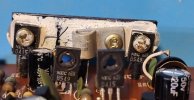

Yes, the c853 is the bias correcting transistor in this unit. So, it "monitors" the temperature on that metal bar that the drivers are attached to. In short, though it may look better to use your plan, it won't function as intended. You will need to drill a new hole in the metal bar when using the BD139 to replace the 2sc853 due to the offset nature of the screw in its mini heatsink. If you look back at p.2 post #38, you'll see the picture of the original hole vs how the BD139 lines up on the metal bar.

ikarus75
Active Member
Okay. But the three transistors should be mounted on the heat sink with insulating washers, right?Yes, the c853 is the bias correcting transistor in this unit. So, it "monitors" the temperature on that metal bar that the drivers are attached to. In short, though it may look better to use your plan, it won't function as intended. You will need to drill a new hole in the metal bar when using the BD139 to replace the 2sc853 due to the offset nature of the screw in its mini heatsink. If you look back at p.2 post #38, you'll see the picture of the original hole vs how the BD139 lines up on the metal bar.

if they are plastic cases with no exposed metal then noOkay. But the three transistors should be mounted on the heat sink with insulating washers, right?
ikarus75
Active Member
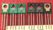
The HK730 is working at 99.5% of its capacity. I have installed the 1220/2690 transistors , set the bias and measured the DC offset.
On the left channel, it is now around -5mVCD; on the right channel, it is somewhere around -30mVDC.
After switching off, the DC offset falls very quickly to 0mVDC on both channels. All good now!
There is still a very short hum, lasting less that a second, on the left channel when the receiver is switched on.
The sound is great, but I want to get the left channel down to almost 0mVDC, as well.
I replaced in the power amp board old 1s2076 with unmatched 1845s some days ago (see one of the first posts here in this thread....didn't have a tester yet (dca55 arrived today) and there were too few 1845s avavailable). I will get a lot of them next day an try to install matched pairs.
I want to replace the 4 main capacitors, but I am a bit afraid to make a mistake. It is not clear right now because there are two pins compared to the old ones with three.
I have ordered 4 4700μF with snap in pins at a 10mm distance. Any advies or additional pics from you guys would help!
Another question: can I use 2A fuses at the main caps fuse holders at 230V mains power here in Austria? The correct value should be 1.25A, right?
I have only 1 and 2A fuses right now available. Better to use 1A?
Last edited:

ikarus75
Active Member
Am I right here...? @jheu02
- Insert the new capacitors with the positive pole into this area through the holes and solder them (RED).
- Insert the negative terminals of the new capacitors into this area through the holes (BLUE) or connect them nearby to this point/conductor track with a wire.
- The dummy holes simply remain open. Or use the negative terminal through the dummy holes of the old one and solder a wire to the blue points/conductor track?
The new capacitors have the same diameter as the old capacitors.
Your starred pads above are the stabilization pads for the third pin on the old caps. As long as you correctly hook up the positive and negative pins, you will be fine. IIRC, the OEM cap sleeves say something like negative lead black or it might have a number. When you pull the cap, the terminals will have one terminal with black paint, or the number, stamped in it, or they might even have + and - stamped into it.
The problem with using snap in caps with 10mm lead spacing is that the hole spacing in the board is 12.5mm. To give greater stability (since bending the snap pins will leave little to solder to) you can either:
Drill a new hole(s) in the existing solder pad(s) for each cap IF you can make the spacing work
Drill holes that are connected to nothing (perhaps the stabiilty pad is 10mm from one of the other pins even) and then run a jumper wire to the correct connection
Purchase leaded caps vs snap in that already have 12.5mm lead spacing like i and others have done. I think 6800uF/63V caps are what I used (UKW on one, UVR on another since the KWs werent available).
In short, yes, what you said above is correct, as i reworded unnecessaritly.
Also, for other pics, search for 730, titles only, dlucy as the member. Doug has good pics of what he did for just your situation using snap in caps. I chose exact lead spacing since I could with the increase in capacitance and voltage, though i think it was the voltage that had more of an effect on the lead spacing in the caps I chose.
My A402 6800uF/63V KW leaded caps with 12.5mm spacing that fits perfectly withoutdrilling new holes or running jumper wires...
The problem with using snap in caps with 10mm lead spacing is that the hole spacing in the board is 12.5mm. To give greater stability (since bending the snap pins will leave little to solder to) you can either:
Drill a new hole(s) in the existing solder pad(s) for each cap IF you can make the spacing work
Drill holes that are connected to nothing (perhaps the stabiilty pad is 10mm from one of the other pins even) and then run a jumper wire to the correct connection
Purchase leaded caps vs snap in that already have 12.5mm lead spacing like i and others have done. I think 6800uF/63V caps are what I used (UKW on one, UVR on another since the KWs werent available).
In short, yes, what you said above is correct, as i reworded unnecessaritly.
Also, for other pics, search for 730, titles only, dlucy as the member. Doug has good pics of what he did for just your situation using snap in caps. I chose exact lead spacing since I could with the increase in capacitance and voltage, though i think it was the voltage that had more of an effect on the lead spacing in the caps I chose.
Recapping and repairing a Harman Kardon 730 twin power series stereo receiver
Just like with the other "twin power" series models, the hk 730 has two independent power supplies. Each has it's own power transformer, bridge rectifier, power reservoir or filter or smoothing caps, and two slow blow fuses. The visible portion of the two power supplies are identical. One...
audiokarma.org
My A402 6800uF/63V KW leaded caps with 12.5mm spacing that fits perfectly withoutdrilling new holes or running jumper wires...
Harman Kardon A-402 Restoration
I just received this amp and want to give it a listen before I start the restoration. As always, I first checked it on DBT, no shorts. Then DC Offset... both channels were over 100mV...hesitant to hook to speakers. Then check Bias IAW the SM to see if that could be affecting the DC Offset in...
audiokarma.org
Last edited:
ikarus75
Active Member
I'm currently considering whether I should get this kind of protection for the HK730...what do you think?
 device.report
velleman K4700 Speaker Protection Kit User Manual
velleman K4700 Speaker Protection Kit User Manual
device.report
I replicated the protection relay from the Rotel RX-800 on the first A-402 I rebuilt, but I didn't find it make much of a difference. There might be some interaction between the "soft start" circuit and the protection relay. My workaround now is to just have the speakers off prior to powering the amp on and off.
ikarus75
Active Member
Today, I finally got round to swapping the main capacitors. I found a way to put in the new ones (KEMET, 4700uF, 63V) and then desoldered the old ones, marked the plus/minus and soldered in the new one.
The bias is OK and the DC offset looks OK too. I hooked up the old phone to the aux and fired it up.
The following is what I heard:
No volume: I hear sound from the left channel. Pulling up the volume, the right channel comes up, but I think the sound is not right. Balance: left right also shows strange behaviour. The left channel plays when there is no volume, or I rotate the balance pot to the right. ****, I must have made something wrong. I am angry because I thought the 730 was now at 100%.
Here is a first picture from the board... :-(

ikarus75
Active Member
Reworked — still the same issue on the left channel.
I removed the Pre Out and Main In jumper and tested with an iPhone — the power amp works fine.
Something must have happened to the preamp... holy sh...
I measured the Pre Out outputs while playing music through the AUX input:
Left channel: constant around 5 mVAC
Right channel: changes with adjustments to the volume or balance controls
The left channel’s volume increases only slightly, and turning the balance knob has no effect on the measured voltage at the left channel’s Pre Out.

I found twelve of these. I need to research how to build a test circuit for matching. I don't have a transistor tester to hand right now
View attachment 3617033
I did this, when I had to produce matched diff-amp pairs for my old HK Citation 12 amp:

It worked great. We actually managed to completely ELIMINATE the turn-on thump these amps almost always have (they also have no protection/ startup relay on the speaker outputs, like is true with the 730).
Regards,
Gordon.
ikarus75
Active Member
Do you know what causes this? @jheu02 @mrk229 ?Reworked — still the same issue on the left channel.
I removed the Pre Out and Main In jumper and tested with an iPhone — the power amp works fine.
Something must have happened to the preamp... holy sh...
I measured the Pre Out outputs while playing music through the AUX input:
Left channel: constant around 5 mVAC
Right channel: changes with adjustments to the volume or balance controls
The left channel’s volume increases only slightly, and turning the balance knob has no effect on the measured voltage at the left channel’s Pre Out.

ikarus75
Active Member
Idea: I will connect an old NAD 3240PE as a preamp to the HK, and vice versa. I will try the HK preamp on the NAD's main input to ensure that the problem lies with the HK preamp.

Left channel is dead somewhere. But you know that. I can't see how simply changing the filter caps would cause this.
How are you measuring the levels at the pre-out jacks? Is it with a scope or meter?
If you have a scope you can signal trace backwards from the pre-amp out jack. Or you can skip around to find the general area and then zoom in.
You can do this with a meter set for AC but a scope is better.
Fortunately we have a good channel for comparison.
It would be best to use a fixed level tone as it is much easier to detect and compare the level differences.
I vote we skip around and see if we can eliminate whole blocks.
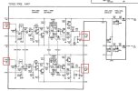
Find these points (red boxes) on the tone/ pre-amp board.
Check the L and R input points on the left of the diagram. They should be the same level.
These test points are before the volume control so it will be high level.
If the levels match then the input switching is all ok and the audio is intact coming into the tone/pre-amp.
Move to the next test if all is OK, if not then the trouble is before the tone/pre-amp.
Go to the output points on the right and check again. The volume control is in play here so the levels should match and go up and down with the control.
If both sets of points are good then we have eliminated the input switching and the entire tone/pre-amp board.
Let us know what you find.
How are you measuring the levels at the pre-out jacks? Is it with a scope or meter?
If you have a scope you can signal trace backwards from the pre-amp out jack. Or you can skip around to find the general area and then zoom in.
You can do this with a meter set for AC but a scope is better.
Fortunately we have a good channel for comparison.
It would be best to use a fixed level tone as it is much easier to detect and compare the level differences.
I vote we skip around and see if we can eliminate whole blocks.
Find these points (red boxes) on the tone/ pre-amp board.
Check the L and R input points on the left of the diagram. They should be the same level.
These test points are before the volume control so it will be high level.
If the levels match then the input switching is all ok and the audio is intact coming into the tone/pre-amp.
Move to the next test if all is OK, if not then the trouble is before the tone/pre-amp.
Go to the output points on the right and check again. The volume control is in play here so the levels should match and go up and down with the control.
If both sets of points are good then we have eliminated the input switching and the entire tone/pre-amp board.
Let us know what you find.