• The move to the new server is done. There are some software and database maintenance updates in process. This has us passing the hat around to help out. We appreciate any donations. Seriously, even a dollar helps. The payment page may be found here - https://www.audiokarma.org/support.html

Harman Kardon 730! Sweet! But, one troublesome channel...

JB8

Well-Known Member
Just picked up my first 730, stoked! I've had loads of 330c's and 430's, even picked up a 330B the other day, but wow, I was so excited to get this 730 even though its condition was the dreaded "untested".

I'll cut to the chase here. The left channel is blowing it's fuses. When I first plugged the unit in to get a baseline it was clear the unit hadn't been cared for lately - really difficult to turn the dial knob and function selectors, dial point light out, most other lights out as well, but, the signal meter is working, stereo light coming on appropriately, so with fingers crossed I attached some test speakers and got great clear sound from the right channel, nothing from the left across all functions. I then pulled the case, pulled the faceplate and started dusting and cleaning pots and push buttons. At this stage I hadn't noticed the blown fuses (it had been a while since seeing a blown slow blow, the element was still intact so at first glance the looked fine, rookie move!). After cleaning I did a quick continuity test on the fuses and found the left fuses were burnt out. I had a spare set of fuses, popped them in hoping a replacement was all it needed, blew them out too.

Some of you may know me by now but I'm early on my path to learning troubleshooting across several brands (while also renovating a house and helping to raise two small wonders), so I still have some significant voids in my knowledge of process/technique, but I love this stuff and I'm committed to learning.

I have a DMM, a scope with one good channel, just built my first remedial DBT, using a Hakko iron and sucker, ready to get after this. I have 5 of the 2.5 A fuses in-hand with a Digikey order for more fuses, but would sincerely appreciate some advice on how to avoid blowing any more as testing occurs.

Thanks in advance, and you're welcome to those of you who like pictures, I feel like it helps tell the story.
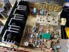
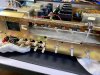
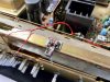
IMG_0073.jpg IMG_0074.jpg IMG_0075.jpg IMG_0076.jpg IMG_0077.jpg IMG_0072.jpg

(at some point someone at a repair shop super glued in a new lamp for the dial pointer, I'm still salvaging the part, still needs attention...)
 
Last edited:
Register to hide this ad
I like those odds, @cademan, I'll do some probing and provide an update.

Thanks for the quick response, much appreciated!
 
Pulled both of the output transistors from the left channel for testing, nothing too wild.

2SD388
+B, -E = .53 v
+B, -C = .529 v
OL on remaining combo's

2SB541
-B, +E = .518 v
-B, +C = .487 v
OL on remaining combo's

Assuming these values are fine or are the 2SB numbers too low?
 
Without pulling data sheets, you would generally check for shorts with the diode setting on the meter between the Base & Emitter. There is a more thorough test on the internet and I also believe a sticky thread here. Also check the drivers and emitter resistors on the bad channel. I would also compare them with the good channel.

Those numbers look okay and if you tested them thoroughly, then check the diodes/bridge rectifier and main filter capacitors on the bad channel. Since this receiver uses a dual mono design, it would be easy to compare readings between the good and bad channels.

Worst case scenario, bad power transformer. Hope not.
 
  • Like
Reactions: JB8
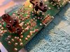
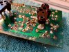
The diodes on the rectifier tested fine (in chassis), but when I pulled the power amp board I found that someone had re-capped it at some point, but they weren't consistent with the replacement caps and new values were really juiced up and not balanced, here's a look.

C401, 402 100uF/10v replaced with 100uF/16v on right channel, 100uF/25v on left channel
C405, 406 220uF/6.3v replaced with 220uF/25v on the right channel, 220uF/16v on left channel
C407, 408 1000uF/10v replaced with (shockingly) like values for both channels
C411, 412 100uF/6.3v replaced with 100uF/16v across both channels

I've been aware of bumping up cap voltage values while maintaining the uF values, but does this seem acceptable?

Love how the power amp board is can be removed, looks like I just need to remove the main output transistors to separate the board from the heat sink?

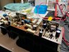
IMG_0079.jpg IMG_0080.jpg

Definitely want to check out the transistors as well, great call.
 
Last edited:
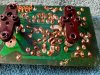
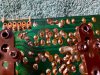
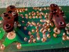
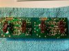
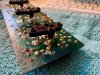
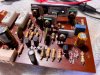
Pulled board from the heat sink to get a good look at the solders, etc. and I'm no expert here, but it looks to be a total mess. So many shoddy solder points, not sure where to start! My gut says I want to balance out the caps, replace where necessary to get them even on both sides, then re-solder/clean up the wonky looking spots, testing components along the way. Thoughts?

IMG_0084.jpg IMG_0085.jpg IMG_0086.jpg IMG_0087.jpg IMG_0088.jpg IMG_0089.jpg IMG_0090.jpg IMG_0091.jpg IMG_0092.jpg IMG_0093.jpg
 
Tested as much as I could and replaced the two sets of caps just for my own piece of mind. Cleaned up some weird looking solders as well.

Findings revealed that nearly everything was fine except for the transistors @avionic highlighted. Specifically, the two 2SC853's really produced some strange numbers, even on the right channel. I double checked the pinouts to make sure what I was seeing was being correctly tested. For instance, measuring -B / +E I was getting a loud beep and readings of .076 v on the left, .109 v on the right, but for +B / -C I got .61, so go figure. The other transistors in that section tested fine, so I'll replace both the 853's and put everything back together and see how it goes.

I believe the replacement is BD139, if this is not correct please let me know, would love to get this beauty rocking again!
 
Update:

Replaced the 2SC853's with BD139's as soon as they arrived, installed them, put everything back together, popped in some new fuses, but this time, ran the power through my crude DBT (using 60 watt bulb). Results were that the light bulb flashed for a moment then went dark, then slowly it began to glow again and flicker some. Looks like the fuses were spared but I'm not really sure how to interpret the results? Was the bulb drawing more power than the amp, so that's why it lit up or should I still be looking for the short that was causing the left channel fuses to blow in the first place?
 
Last edited:
There's still something drawing too much current in the amp, that's why the bulb is glowing. I didn't see an issue with the caps...probably jus what the prior owner/"fixer" had on hand. Though I do keep some 16V caps on hand for the 6.3 and 10V caps, I usually go with a minimum 25V cap (the 16s are usually smaller especially when capacitance goes up. Personally, I would have increased the voltage on the 1000uF/10V caps to 25V (which I did on my A-402 restoration), but the other increases were fine. You'll need to re-drill the heat sink so the BD139 can attach due to the offset nature of the OEM. See here at post #138
 
Thank you, @jheu02, appreciate the heads-up on the cap values. I'm still learning what's suitable for upgrading of voltages and will consider your practice when I replace more of them, makes perfect sense.

Specific to the BD139's, I'd read that they really didn't need their own heat sink or an attachment to the existing heat sink, but if necessary I can certainly figure something out. Candidly I'm more fixated on determining what's drawing the excess current. I guess I'll just keep roaming from channel to channel comparing voltages and testing for failures and see how it goes. I have faith that this guy can be saved, will just have to knuckle down and be patient.

Can you confirm that ultimately I'm looking for the bulb to surge on at power up but then go dark right after, in order to determine a healthy system? That basically having the light burning even slightly after the initial flash means there's still an issue?

If you have a typical path you take when tracking down this kind of issue please send it on over, any experience and advice always tends to speed up the process! Thanks again!
 
Quick update, I saw the other AK thread on a 730 also blowing fuses. When he pulled the amp board the DBT would flash then stay dark, which is a good thing? He then shotgunned the board and it fixed the issue, no more fuses blowing.

I've since pulled the amp board again to dig in a bit. Not quite shotgunning it but I did replace the other caps due to some really ugly solders.

When comparing the IN/OUT points across both channels I'm getting .40 DC volts on the left, -.22 DC volts on the right (the good channel). I'm not great at testing components but to me this is a good sign in that I would assume they would ideally share the same values, even if testing for DC volts isn't necessarily the best way to compare? Good news in that if both channels had the same reading the issue may actually on a different board (which I imagine it still may be).

Considering the amount of mucking around that appears to have happened with this amp board I'm struggling to figure out where the issue is. Should I start pulling resistor legs to test? The VR's had been replaced, is there a good way to test them and are they ever an issue?

IMG_0154.jpg IMG_0155.jpg
 
Another update! (I'm gonna keep hitting this thread with anything I find. Getting crickets mostly, feels like this is one of those scenarios nobody likes because it's a needle in a haystack, ha!)

In comparing the amp board side by side I couldn't identify any components on either side that were clearly failing, so I tried to clean it up a bit more then reinstalled the board and ran things for a while through the DBT. Still the same thing happening, starts up, bright surge of light in the bulb, bulb goes dark then comes back up in a couple seconds to a fairly strong, yet still orangey hue. The only significant reaction I noticed in the lights were that if, when listening to FM, if I bumped the treble I got no reaction, but if I pushed the bass to full clock wise position the lights in the receiver would dim and the DBT would burn brighter until I backed the bass off. Could this mean there's a tone board issue?

Just hoping for a few tips to help track down what ever's pulling too much current otherwise I may need to just put this thing in the closet for now and move on to the next project. Thanks all, I appreciate your help!
 
What wattage bulb are you using? If < 100W, that might be the issue. A 25W-60W bulb for things like preamps and tuners. 100W to 150W and up for amps.
 
Thanks, John, great call, exactly what I needed to know. I've been using a 60W bulb, will bump up the wattage and see how it goes.

So I should be looking for early DBT flash on power up, then totally dark bulb once the receiver is fully powered up?
 
Thanks, John, great call, exactly what I needed to know. I've been using a 60W bulb, will bump up the wattage and see how it goes.

So I should be looking for early DBT flash on power up, then totally dark bulb once the receiver is fully powered up?
@JB8 where you able to figure out what the excess power draw was on one channel?

I have a similar issue and can’t figure out what is causing it. Hopefully you have fixed yours.

Also on your B139 replacement photo , I could be wrong but looks like you have it installed backwards, metal side should face the heatsink.

Thanks
 
I got rid of that unit some time ago, no idea what the issue(s) were. Great receiver but it was a mess.
 
Back
Top Bottom