• The move to the new server is done. There are some software and database maintenance updates in process. This has us passing the hat around to help out. We appreciate any donations. Seriously, even a dollar helps. The payment page may be found here - https://www.audiokarma.org/support.html

Harman Kardon 930 Short out - need help!

The voltage from the filter caps measures 36-37V, while the specs asking for 39v. I don't know if this is close enough.
Can I test those resistors, trimpots (you mean the bias adjust resistor right?), and transistors on the board? If the trimpot is bad, what the replacement part I can use?


You've gotten good advice.

The varistors certainly could be the source of the problem. The emitter resistors and the trimpots are also potential culprits. Or a loose / broken connection somewhere. Really erratic behavior has twice, for me, come from a broken wire Lead right at where it connected to a board, was effectively invisible, and connected MOST of the time and disconnected at odd (when moved) times.

Good luck!
 
Ok, in simple power supplies the DC output is two terminals: a ground post (GND) and a positive post of some number of volts. That positive side can be thought of as a "rail".

In more modern power supplies, you need a positive X number of volts and a negative X number of volts. These power supplies have three output posts: a positive "rail", a ground, and a negative "rail". If the positive rail is labeled as "+39V" then reading between the positive output post and the ground post you should read 39 volts. If you read between the ground post and the negative post, you should read -39 volts. The total output of that power supply is 39 volts plus 39 volts, for 78 volts, the total potential difference between the positive rail and the negative rail.

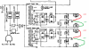
Your "twin powered" HK 930 has TWO power supplies, so you have four readings to make to verify each of your rails is outputing the correct amount. I've labeled the image below for you with where to measure to and from and how much you should read on your voltmeter.

HK 930 power supply.png

If you get 34 volts and - 34 volts from one power supply, that's OK but a little disappointing. It isn't so low that your receiver won't work, but it is lower than spec and will reduce (a little) the max volume output you'll be able to get.

If your +B2 and -B2 voltages (that's one power supply circuit) and your +B1 and -B1 voltages are similar (that's the other power supply in your twin), BUT the B2 voltages are much different than the B1 voltages, let's say 34V from the B2's and only 29V from the B1's, then you should consider rebuilding the power supplies.

If they are close to spec, within 6-8 volts of 39 volts, and they are close to each other, then you're OK for now.

And just so you know, those really big capacitors, I think they are C405 to C408, those are your power reservoir and primary filtering caps. They take the very choppy DC voltage coming right off those rectifier diodes, store it up, and deliver a much smoother DC voltage to the output terminals of the power supply. These are large electrolytic caps and they will one day fail. I can't read the value on the schematic, but they are probably 4400 uF to 6800 uF in capacitance and 50V. If you were replacing them, and they were 6800 uF, then you'd look to replace them with a high ripple (to make the DC as smooth as possible) and low ESR (lower internal resistance so less of the current flowing through them dissipates as heat) series like Nichicon LLS1J682MELA for $4.54 each.
 
Can I test those resistors, trimpots (you mean the bias adjust resistor right?), and transistors on the board? If the trimpot is bad, what the replacement part I can use?

You can test the resistors by desoldering one leg of the resistor, pull that leg away from the circuit board, and then using the ohm setting on a multimeter to measure from one leg (still in the board) and from the other leg (sticking up into space). Your measurements should be within 20% of the schematic value. A measurement of further away than that indicates drift (and you should replace that resistor) and a measurement of 0 ohms (a short) or infinite ohms (a break) means you have to replace the resistors.

Measuring the trimpots is harder. You have to desolder the entire trimpot and remove it before measuring it. For trimpots with three legs, use the ohm setting on your multimeter and measure from the left leg and the right leg. The resistance value you get should be the total max resistance of the trimpot. A 5 K trimpot should always measure 5 K ohms (give or take 20%) from one leg to the far leg. It it measures less than that, measures zero, or measure infinite, you'd replace it.

To properly test a trimpot with three, you would next put one of your leads on the middle leg and watch the resistance value as you move the trimpot's dial or screw. It should *smoothly* move from zero or very low ohms to the max value of the trimpot. If you get jumpy values as you move the trimpot, ESPECIALLY if it jumps back and forth between zero and some number, then you may have a pitted or badly oxided trimpot. That can spell doom for your expensive output transistors as that trimpot accidentally drops to zero ohms and lots of current flows when only a little was expected. This is one of the common problems with power amp boards with adjustable bias.

Test the trimpots and if they are bad or unreliable, we can work on which parts are best for a replacement. New Bourns trimpots are typically only $1.50 to $3.50 each.
 
I dug out the junker I got (it actually works, mostly)

There is a pair of boards mounted to the heat sinks on either side of the amp board.
Those are the varistors.
Service manual shows them as D601/2 and D621/22
They are KB265
Those I am unfamiliar with but usually a pair of 1N4148 in series is a good replacement for blob diodes.
The trouble is, there are 2 blobs in parallel so measuring them doesn't tell me much.

I suspect one or more of yours are whacky.

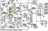
In the schematic the varistors are here:

HK 930 power amp 002 varistors.png
(be sure to keep in mind that the above image is just one half of the power amp board. You've got TWO varistors per channel and TWO channels).

If these are indeed flaky, you'd use this thread to make an equivalent varistor from two diodes, just as @blhagstrom is suggesting: http://audiokarma.org/forums/index.php?threads/replacing-the-stv-3h-and-4h-diodes.279530/

What I don't know is how to test a varistor to see if it is 1) working at all or 2) working properly (changing current flow as the ambient temp changes). Maybe the above "how to make your own STV-3H" thread will help you understand how to test your varistors. The current value you get from yours will be different than a STV-3H but it should behave the same way.
 
In the schematic the varistors are here:

View attachment 1099573
(be sure to keep in mind that the above image is just one half of the power amp board. You've got TWO varistors per channel and TWO channels).

If these are indeed flaky, you'd use this thread to make an equivalent varistor from two diodes, just as @blhagstrom is suggesting: http://audiokarma.org/forums/index.php?threads/replacing-the-stv-3h-and-4h-diodes.279530/

What I don't know is how to test a varistor to see if it is 1) working at all or 2) working properly (changing current flow as the ambient temp changes). Maybe the above "how to make your own STV-3H" thread will help you understand how to test your varistors. The current value you get from yours will be different than a STV-3H but it should behave the same way.

Varistors like this test like series diodes.
Flacky ones test fine on a meter but the amp keeps blowing fuses, or lighting a dim bulb.
Flacky ones suck balls.
 
It's AK'ers like you that just amaze me. Man! You've got everything!

I am now hooked into the WA state recycle program and my connection cleaned out a repair shop that moved.

I am buried in junkers now and many are low life junkers.
The 930 was surprising but half stripped and the tuner was whack.
She's parts now.
 
Again, thank you so much for the detailed write-up! You and blhagstrom have been really helpful. And AKers like you are the reason that I can continue this effort.

I’ll just replace the varistors. Desoldering these and test is already more than half the effort.

In the schematic the varistors are here:

View attachment 1099573
(be sure to keep in mind that the above image is just one half of the power amp board. You've got TWO varistors per channel and TWO channels).

If these are indeed flaky, you'd use this thread to make an equivalent varistor from two diodes, just as @blhagstrom is suggesting: http://audiokarma.org/forums/index.php?threads/replacing-the-stv-3h-and-4h-diodes.279530/

What I don't know is how to test a varistor to see if it is 1) working at all or 2) working properly (changing current flow as the ambient temp changes). Maybe the above "how to make your own STV-3H" thread will help you understand how to test your varistors. The current value you get from yours will be different than a STV-3H but it should behave the same way.
 
Changed the diodes for varistors today, and now the receiver has a short somewhere. The dim bulb lights up, not as bright as initially when the bridge rectifier had a short. Tested the varistors I just replaced and they seem to pass the diode test, showing 700mv one way, and OL the other way.

What can be wrong now?
 
Last edited:
I just realized that, and changed it to 2 diodes in series and then parallel, so total 4 diodes in one channel. Still same issue. The light bulb is lighting up, not very bright though.
 
The short maybe somewhere else I think...Maybe when I did it wrong the first time, something got toasted? I didn't hook up any speaker though
 
At this point, I would start at the outputs and work my way back through the drivers and pre-drivers and feedback and differential pair. Basically all the transistors. I would check all the diodes and then probably all the resisters.

You did make replacements by hooking 2 diodes in series, right? Did you test the replacements? I don’t know if 700mv is compared to the new parts.
 
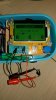
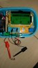
This is what I made, and they both tested about 1.35v.
 

Attachments

  • 20180201_193223.jpg
    20180201_193223.jpg
    42.3 KB · Views: 75
  • 20180201_193515.jpg
    20180201_193515.jpg
    41.3 KB · Views: 72
I think the replacements are more than enough but we are only going by the measurement off the old ones.

We’re probably beyond some simple issue here.

We’re in the hard core voltage tracing and/or piece by piece testing but even then we may not find it without a curve tracer.
 
Well, this is probably beyond me then... The hard part is that 930 circuit board is extremely complicated with wires running on both sides of the receiver. I'm afraid I can easily break something when fixing something. To disconnect the pre-driver board, I have to disconnect a bunch of wires, which will be very time consuming.

Maybe I should get a 730 instead, which has a much cleaner design.
 
OK, I tried one more time by putting back the old varistors. The receiver returned back to the old state. The short is gone, and the DC offset at the speaker posts now measures 89mv and 30mv, lower than the previous 138mv and 70mv. So I guess the varistors made from the 1N4148 didn't work. One difference I found on the one I made is that it measures uf=1.35mv C=1~2pf, while the original one has uf=1.35mv C=35pf. Not sure what that means...

However, it is still having issue with shorting out periodically, with the dim bulb fully lights up.
 
On some manufacturer's schematics there are voltage markings in many places so you can compare your unit's voltage in each spot with the schematic's voltage. This sometimes leads you to a "hey! I'm only getting 1v at a transistor's emitter where the schematic says I should see 9v!" and that gives you a general area to check in and around to check components. Sadly, the hk930 service manual on hifiengine doesn't have these handy voltages. The places it does have voltages, where they exit the power supply and lead to other boards, is something you can check but I think you've already done that. If not, give it a try. It'll only take a few minutes of your time even though it has low likelihood of a giving up a clue.

The next thing you could do, if you really want to fix this, is to run a mono test signal in via the AUX connector and check the voltage of each board as that signal comes in one side of the board and then as it exits the other side of the board.

Don't have a signal generator or oscillator? No problem. Download a tone generator app of guitar tuning app for your phone, plug the headphone out of your phone to the AUX in, set your phone for max volume, and use the AC voltage meter of your multimeter to "watch" the signal go into and then come out of the tone board, then the preamp board, then the power amp board. Slow work, but it'll tell you, generally, where the first problem appears in the chain of the boards. This is what a signal tracer does, but no need to buy one of those if this is the only time you'd use it; a multimeter and a signal generator app will do.

If that's too much, just post your hk930 on the BarterTown for sale board and bring in some funds to get you started toward a hk730. The 930 is well-sought-after, so it should bring good money.
 
Back
Top Bottom