• The move to the new server is done. There are some software and database maintenance updates in process. This has us passing the hat around to help out. We appreciate any donations. Seriously, even a dollar helps. The payment page may be found here - https://www.audiokarma.org/support.html

HarmAn Kardon Citation 11 - DC on One Output

Phobosx

Phringe
Hi all. I have an oddball problem I was hoping someone may be able to help with. I have a Harmon Kardon Citation 11 Pre-amp. It has been working fine but earlier today I turned it on and one of the meters on my Amp pegged. So I turned it off and checked the cables. Turned it on again and same result. I pulled the Pre-amp out and measured the DC on the outputs. The Right Channel is 0 volts. The left goes to about 3V DC on power up and then starts to drop. After about 20 seconds it had fallen to about 32 mv DC. Luckily the amplifier isn't damaged.

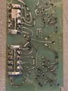
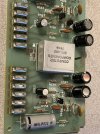
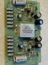
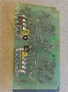
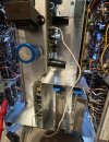
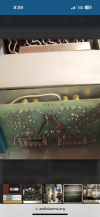
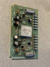
Okay fine I think. It's older and some part (Transistor or whatever) has failed. I open it up and pull out the Pre-Amp board (See pictures). I then download the service manual (from 2 separate sources) and the pre-amp board in the service manual is different. The one I have has this part called "Computer Components" but the pictures of the pre-amp board in the schematic show no such part and is generally different (Different parts, labels, etc) than the picture in the service manual. The Service Manual schematic shows 3 FET's, This board has no FET's.

I checked the 4 transistors on the board (in circuit) and none show a short and measure as I would expect. I checked the electrolytic capacitors (only 4 per channel) and no shorts or opens. I measured each resistor for both channels and they are the same values between right and left. I checked the voltages from the power supply and they are all just about where they should be (+/- a volt or so). The problem channel has a connection for something called " + Control Voltage". The working channel has a connection for "Control Voltage Ground" The schematic has a line for "Control voltage" but gives no value. I don't see anything on the schematic called "Control Voltage Ground". I measured the resistance between the chassis and this " Control Voltage Ground" and its 50 K Ohms so, this is likely not tied to ground like the other NEG Voltage pins are. I Also measured the AF Input of this board on each channel and it's near 0 DC Volts. Now, if I measure between the chassis and this "+ Control Voltage" it's about 86 volts. If I measure between the chassis and the "Control Voltage Ground" it's around 66 or so.

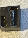
My luck would be the problem is in the " Computer Components" module. The AF output and Output ground both go into this "Computer Components" module. I could probably de-solder this and maybe open it up but Id rather not go that route right away as I may damage it.

Has anyone run into this type of thing before? Any idea how to check this? The schematic in the service manual does not match the circuit on my board so that information is probably not very useful.

Thanks
 

Attachments

  • IMG_8445.jpg
    IMG_8445.jpg
    193.4 KB · Views: 13
  • IMG_8447.jpg
    IMG_8447.jpg
    141.7 KB · Views: 13
  • IMG_8446.jpg
    IMG_8446.jpg
    148.1 KB · Views: 13
Register to hide this ad
The three JFETs are for muting and that's probably what the module is doing. The audio circuit looks like it might the same as the schematic I'm looking at. Using the schematic you have check the voltage at the collector of Q505 and Q509, both have a 5.6K resistor connected, should be approx. +24VDC. They should be the transistors closest to the twin black capacitors. If that's good quickly check the outputs of C515/516 and C523/524. I guessing one of those capacitors is bad and not blocking the DC at start up.

Craig
 
Thanks, but there is no Q509. This seems to be a later version of the Citation 11. The service manual / schematic I have is wrong. It appears to be for the earlier model. The earlier model (From what I can tell) has a silver face and a dark face where the EQ is. Mine has a silver face and a slightly different hue of silver where the EQ is.

Those 3 JFET's seem to have been replaced with this "Computer Components" box. This board does not look at all like the board in the service manual. C523 and C524 on my board are ceramic disc capacitors. In the service manual I have they are listed as 10 Uf 35/ Volt. There is no C516 either. I do have a C515 but it's a 5Uf 35 V and looks to be right at the AF input to block DC.

The power supply board is Different too. The power supply I have, has a Q801 transistor (Motorola 29832 - Which is another part I can find no information on) along with a couple extra parts. There is also a white wire coming off a pin on the power supply board that goes to the Pre-amp board that isn't in the earlier versions of the Citation 11.

I have been looking for a service manual or schematic for this later Citation 11 but, no luck yet . The Service manul / Schematic I have is from HIFI Engine and I found a similar one from Elektronica (I think). Both are for the earlier versions of the Citation 11.

I have attached a better picture to show the parts on the board I have.
 

Attachments

  • IMG_8454.jpg
    IMG_8454.jpg
    165.1 KB · Views: 6
Though the part desiginations are different the circuit might be the same. Check for +24VDC on the collectors of the transitor closest to the two black capacitors in each channel. Those capacitors are the output capacitors, C515,516,523,524 on the schematic. I can see from your pictures that most of the amplifier circuit parts are the same values that are on the schematic. You have one good channel to compare with.
 
Checked each one. It takes a few seconds to get up to 24V DC but it does get there. Also... now it seems BOTH channels have a DC output voltage issue. So while this DC Voltage makes the meters go up on my amp, I have this pre-amp output running into the AUX of a old expendable receiver that seems to handle the DC fine and I can hear sound. What is odd, is this used to have a sort of ramp up with the sound. It started out soft and after 10 or so seconds it would be full volume. Now, the sound comes out of Output jacks right away and at the correct level (The level is based on what the volume is set at). It's like the slow ramp up in output level and delay is gone.

I wonder if some component of that delay function has failed and taken out something on the output board thus causing the DC level. Or maybe the DC level I see IS from the delay circuit since the voltages does drop down to a negligible amount after about 15 seconds.

And the unit still sounds great. No HUM in the sound or anything .

In comparing my circuit to the schematic, my circuit it not like this. The Collector of the transistor (Q506 and Q508 on my board) does not to to the AF out like it does on Q505 and Q509 on the schematic. It goes into this little silver box marked "Computer COmponents) and then the bottom of the box goes to the AF Out. See the picture. The Green circles are where the outputs from the 2 capacitors in series go Into the silver box. The Yellow are there the output pins are on the board. The black is the Output ground (AF ground) . The signal appears to travel through this silver computer components thing.

The output has to be getting the DC from there. In looking at the 2 caps after the Collector of the transistor I don't see how DC could even be present at the output unless the caps were bad.
 

Attachments

  • IMG_8457.jpg
    IMG_8457.jpg
    154.6 KB · Views: 5
Well, this is odd. Now the spike to 2.5 or whatever volts on power up is gone. The outputs have .1 volts for about 5 seconds then I hear something make a noise (A small click) right where that silver box is and the outputs jump to 500 mv but start dropping from there. And it sounds great too.

At this point I am going to maybe clean all these contacts where the boards plug in. Having these unplug is handy for servicing but I guess after 50 years maybe there is some corrosion or dirt or something causing a intermittent issue. I'll re-cap this too as maybe a cap is going bad and causing these problems. I'll start with the power supply and see what happens. There are a few parts on the power supply board which feed a white wire that goes from the power supply board to this Output board and the lug is connected directly into this mystery silver box. This wire is also not on the schematic and neither are these extra power supply parts.
 

Attachments

  • IMG_8458.jpg
    IMG_8458.jpg
    157.7 KB · Views: 4
Maybe it's muting the output instead of the input like the earlier version. The click sounds like a relay. DeOxit the connectors.
 
Maybe it's muting the output instead of the input like the earlier version. The click sounds like a relay. DeOxit the connectors.

Both the AF OUT and the AF Ground go into this box so, I guess it may be muting the output.

I don't know of I can open this up without damaging it. It looks like a metal case that is sealed underneath. And it's a very faint click. Maybe a very small relay but if it's a relay why does it say Computer Components on the top? Maybe that's the manufacturer and not a part description?? I have seen a post on this site I think where someone had bypassed this thing (See pic) . I may try that if all else fails. Maybe remove it from the circuit entirely. I don't really care about the mute when starting. I'd rather not have DC on the outputs.
 

Attachments

  • IMG_8450.PNG
    IMG_8450.PNG
    325.5 KB · Views: 2
I can see from that picture the signal is coming from the two series capacitors in each channel. Monitor those capacitors for DC when turning on the preamp. Also check for bad solder joints on the connectors. I doubt the "box" is causing the DC problem, what goes in the box comes out of the box, GIGO, Garbage In Garbage Out.
 
I was able to unsolder the box and open it up. It was not as hard as I had thought. Whatever is inside is covered in hardened black goop. Looks like a type of small relay.

With this silver box out of the circuit, (Which looks like a relay and it seems after this control voltage gets to some level the relay activates and removes the short on the AF outputs) I measured the caps you suggested for DC and it starts out at 2 or 3 volts then after a moment or two it goes up to 12. I replaced those 2 caps (one at the end of each channel, C516 and C524 on the schematic) but I still get the same.

This is a real head scratcher. the output of C516 let's say, has no other connection other than to the silver box. With the silver box out it has no connection to anything else at all and it still 12 V DC. I have no idea where that voltage can be coming from. There is a R 531 in the schematic and that's not even present on my board.

I reinstalled the relay and it works as before: There is 0 volts on the output until the relay clicks. Once it clicks the DC on the outputs is around 700 to 900 mv and starts dropping.

I am wondering if maybe this is the right behavior, and this control voltage is coming up too fast and triggering the relay too soon. Another 3 seconds in the delay and the DC on the output would substantially lower. If this delay is from some R / C circuit then maybe one of the caps related to this control voltage is bad. The power supply board has quite a few 47 uF 100V caps. I have none in stock so I'll have to order some to replace whats there. And the values on the schematic are off from my board. The schematic shows a 15k 1/2 watt and 10k 1/2 watt resistors (R801 and R802) as part of the Control voltage circuit, which are both connected to C801. On my board these are 470 Ohms and 2 watt resistors. (Also labeled R801 and R802)

There is this Mystery transistor too which looks to be part of this control circuit and that may be bad. It has a Motorola symbol on it but the number is 29832. I can't find a cross reference to that at all. It's called Q801 on the circuit board.
 

Attachments

  • IMG_8459.jpg
    IMG_8459.jpg
    105.6 KB · Views: 3
Well, it's fixed. I replaced the capacitors on the power supply. However, the first one I replaced was the mystery one, C801, which is present on my unit but not on the schematic, and is part of this Control Voltage circuit that connects to the relay. Once that was replaced I tested the unit and the turn on delay went back to the 5 or 8 seconds or whatever it was before and it seems to be working well. My guess is this capacitor was not working as expected and let the outputs turn on too fast while the circuit was maybe still stabilizing the DC.

I then replaced the remaining power supply capacitors. I also replaced the pre-amp board capacitors.
 
Back
Top Bottom