• Please note that Audiokarma will be offline briefly for updates early on Monday morning, September 28th.

Harman Kardon HK 725 preamplifer lamps?

vintagetree

Active Member
Hello, everybody. Thank you very much in advance.

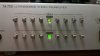
My HK 725 preamp has two lamps burnt, it think, they are out. See the pic from online, should be like this.

I download the service manual, but nothing help, can't find useful information.

Wonder if somebody knows the model of it? I would get two lamps to replace the bad ones.

Best.

harman-kardon-hk-725-3652784.jpg
 
Register to hide this ad
two lamps

I hope someone will come along who has already solved this, but my fear is that you're going to need to guess, and perhaps do some trial and error experiments.

As you may know, the lamps are fed from unregulated DC power supplies, with 1K resistors in series. The resistors are only 1W parts, so if the designers allowed for a decent margin, the current that the resistors deliver to the lamps must only be 20-odd mA. If you measure the voltage on one of the resistors (either R603 or R604, located on the switch boards), and subtract 20V from the measurement, it will give you an estimate of the voltage rating for the lamps. My guess is you're aiming at something like 24V, 20mA lamps. Such things seem to exist, and here's one in a small form factor from a legit supplier:

https://www.alliedelec.com/product/rs-pro/3607929/70643543/

There's also dgwojo.com, a great supplier, but I don't know if he'd have something like these. He's very responsive to inquiries.

Speaking of physical form, have you looked at what it's going to take to access the lamps? I hope they're not actually embedded in the switches.

Oh, and if you might want to look into replacing with LEDs, if you can find some to physically fit. In that case you will need to change R603 and R604 to higher resistance so that they only deliver the small current that the LEDs will need, and the resistors might need to have higher power ratings since there will be higher voltage across them.

Whew, sorry to run on. How many words does it take to change a light bulb? :)
 
I hope someone will come along who has already solved this, but my fear is that you're going to need to guess, and perhaps do some trial and error experiments.

As you may know, the lamps are fed from unregulated DC power supplies, with 1K resistors in series. The resistors are only 1W parts, so if the designers allowed for a decent margin, the current that the resistors deliver to the lamps must only be 20-odd mA. If you measure the voltage on one of the resistors (either R603 or R604, located on the switch boards), and subtract 20V from the measurement, it will give you an estimate of the voltage rating for the lamps. My guess is you're aiming at something like 24V, 20mA lamps. Such things seem to exist, and here's one in a small form factor from a legit supplier:

https://www.alliedelec.com/product/rs-pro/3607929/70643543/

There's also dgwojo.com, a great supplier, but I don't know if he'd have something like these. He's very responsive to inquiries.

Speaking of physical form, have you looked at what it's going to take to access the lamps? I hope they're not actually embedded in the switches.

Oh, and if you might want to look into replacing with LEDs, if you can find some to physically fit. In that case you will need to change R603 and R604 to higher resistance so that they only deliver the small current that the LEDs will need, and the resistors might need to have higher power ratings since there will be higher voltage across them.

Whew, sorry to run on. How many words does it take to change a light bulb? :)

Thanks.

I opened it, and found two very tiny bulbs wrapped with green sleeve.
Measured, It is 37v and 38ma, wonder if it is reasonable?

Thanks again.
 
Measured, It is 37v and 38ma, wonder if it is reasonable?

I'm not at all sure I understand what/how you measured.

If the lamps are burnt out, then any voltage you measure on them will be the open-circuit voltage of the unregulated supplies. The open-circuit voltage is a bit of a help, but you need to account for how much voltage would be dropped across the 1K resistors if there was an intact lamp in place. My guess is that the resistors were chosen to pass no more than 20-odd mA of current, so the voltage drop across them would be about 20V. I still think it's plausible that the original lamps were in the vicinity of 24V, 20mA.

But you give a current measurement, and I'm more curious about that. Did you hook up the meter to the lamp terminals in current measurement mode? That would, in general, be a rather risky thing to do, unless one knows that the current level is going to be OK for both the meter and the circuit under test. In this case, the meter would be pretty safe given the 1K series resistor, but that resistor will have had to dissipate over 1.4W, which is not so safe. Probably no harm done if the meter wasn't hooked up for long.

Or was that a typo, and both your measurements were actually voltages? No worries there.

At least it sounds like the accessibility of the lamps isn't a problem - yay!
 
perhaps it helps?

Nice catch! Sure seems like a help, all right.

Although now the challenge (if sticking with incandescents) is to find 6V lamps that will work on 20-odd mA. Seem to be some on the 'bay.
 
Nice catch! Sure seems like a help, all right.

Although now the challenge (if sticking with incandescents) is to find 6V lamps that will work on 20-odd mA. Seem to be some on the 'bay.
I skimmed the manual, so I can't say for sure, but maybe you are looking for 12 V lamps, since they go from +6V to -6V? The manual is not as clear as it might be on a lot of things!
 
from +6V to -6V

The schematic shows one terminal of each lamp being connected to ground, so it's just that the two lamps run from different polarity supplies.

Why they decided to do that is a curiosity. I guess it has a pleasing symmetry, but it's not like the load is necessarily symmetrical, since one lamp could be on while the other is off.
 
The schematic shows one terminal of each lamp being connected to ground, so it's just that the two lamps run from different polarity supplies.

Why they decided to do that is a curiosity. I guess it has a pleasing symmetry, but it's not like the load is necessarily symmetrical, since one lamp could be on while the other is off.
Got it, thanks.
I like to replace incandescent bulbs when possible, but if no replacement exists, I believe that the attached file shows a way to substitute an LED.
 

Attachments

Thank you so much. Everybody,

I'd like to try a small bulb 24v or 12 v to see which one is nicer. I can't only do some very basic electronic job.

Thanks again.
 
Same....I've found some 6v lamps but the leads are long and they don't really fit the designed space. Thinking maybe LEDs could be a better option with some mods. Will last longer too...
 
Same....I've found some 6v lamps but the leads are long and they don't really fit the designed space. Thinking maybe LEDs could be a better option with some mods. Will last longer too...
I ended up replacing my bad lamp with a green LED. The brightness/color are slightly off, but at least it works, and I don't think anybody notices the slight difference except me.
 
As
I ended up replacing my bad lamp with a green LED. The brightness/color are slightly off, but at least it works, and I don't think anybody notices the slight difference except me.
Replaced as in a straight swap, or did you add more resistors to the circuit?
 
For future reference. The lamp voltage in the schematic is 6V. There is an existing series 1k Ohm resistor R604 that according to the circuit is 32V on the other side, so 26V drop would imply 26mV current. I bought an LED with 2.3v forward current and rated at 20mV, so in theory should have a 180 Ohm in series and 380 Ohm in parallel. I'll start with just a series resistor and see what happens.

[EDIT: I added a series resistor, but only one worked. I double triple checked all the connections, everything was identical for each circuit, I tested the other LED and it was fine...then I remembered a discussion about one circuit being +6V and the other one -6V...so the LED had to be reversed in order to work correctly ! ]
 
Last edited:
Back
Top Bottom