• The move to the new server is done. There are some software and database maintenance updates in process. This has us passing the hat around to help out. We appreciate any donations. Seriously, even a dollar helps. The payment page may be found here - https://www.audiokarma.org/support.html

Harman Kardon hk770 Upgrade Project

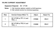
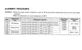
A reading of 24mV across the test points (TP1 and TP3 or TP2 and TP3) is equivalent to ~73mA, IMO, this can be reduced to ~10mV for a bias of 30mA.
I think that you have a bad interpretation of the idling current adjustment procedure on the HK770 service manual. The manual says to measure the voltage at TP1-TP3 and TP2-TP3 and adjust for 24mV total voltage. If the circuit is perfectly balanced it will be 12mV/0.33 Ohm, or 36mA per power transistor, or 73mA of total bias current in the two pairs of power transistors.
 
I think that you have a bad interpretation of the idling current adjustment procedure on the HK770 service manual. The manual says to measure the voltage at TP1-TP3 and TP2-TP3 and adjust for 24mV total voltage. If the circuit is perfectly balanced it will be 12mV/0.33 Ohm, or 36mA per power transistor, or 73mA of total bias current in the two pairs of power transistors.
Even though 73mA seems a bit high, I'm not sure I agree with your interpretation of the manual. The wording is, "24mV +-10% at total voltage". I admit to finding the phrase, "at total voltage" a bit odd, but I have a hard time interpreting it as: "the sum of the two voltages" TP3-1 and TP3-2. I think it does mean 24mV across each of the 0.33ohm emitter resistors =~ 73mA each, or ~145mA per channel. It's also worth noting that other HK amplifiers of the '80s and '90s recommend similarly high bias currents (HK750, HK6100, PA2200).

Curiously, the manual for the SA5050 (almost identical to the 770) doesn't bother recommending a direct idle current setting. They instruct you to hook up the distortion meter (which you of course have in your shop) and tweak VR403 and 404 to minimize distortion...
 
Last edited:
My interpretation of the bias adjustment is correct. There are two pairs of power transistors per channel. There are two blocks of dual emitter resistors, one block is connected to the emitters of the NPN power transistors, and the second block is connected on the emitters of the PNP power transistors. If the NPN and the PNP power transistors are not matched, one transistor will conduct more than the other of the same type. If you measure the voltage between TP1 and TP2, you will have a very low voltage. What the manual wants you to do is to make the sumn (not the average) of the emitter current of both PNP transistors, for each channel.
 
Admittedly, the directions in the hk770 Technical Manual for setting the bias are somewhat ambiguous. However, as mentioned by @The Plumber, Harman Kardon does typically specify high bias settings, and it is often ~75mA. For example, the integrated amplifier in the 700 series (model hk750) does explicitly state that the bias is to be set to 75mA: adjust for 33mV while measuring at the test points (i.e., across both 0.22ohm emiter resistors). Similarly, the idling current setting for the hk870 power amplifier (with 4 power transistors in its output stage) is 75mA: adjust for 50mV while measuring at the test points (i.e., across both 0.33ohm emitter resistors); the bias is confirmed by measuring at the second set of test points that are across the other set of emitter resistors. Hence, from reviewing the hk750 and hk870 Technical Manuals, it is reasonable to conclude that the intented bias for the hk770 amplifier is indeed 73mA, i.e., adjust for 24mV across a 0.33ohm emitter resistor.

From hk750 Technical Manual, pg. 2
hk750 bias.jpg

From hk870 Technical Manual, pg. 3
hk870 bias.jpg

Detail from hk870 schematic, showing test points
hk870 output stage.jpg
 
Picking up this thread again....I've been having issues with the amp cutting out (mine is a SA5050) so decided to recap it and reflow the solder joints.

I bought a bunch of caps, but was confused by C401/402 on the main amp boards, which don't appear in the parts list of the manual (either hk770 or Silver SA5050). It's a 100uF 10V ELNA, which appears to be bipolar? I can see that others have replaced this with a film resistor, which seems to be 4.7uF. Is there any explanation as to why it's a different type/value, and am I correct that it is bipolar, as I've bought polarised replacements...


1712401635417.png
 
...was confused by C401/402 on the main amp boards, which don't appear in the parts list of the manual (either hk770 or Silver SA5050). It's a 100uF 10V ELNA, which appears to be bipolar? I can see that others have replaced this with a film resistor, which seems to be 4.7uF. Is there any explanation as to why it's a different type/value, and am I correct that it is bipolar, as I've bought polarised replacements...
See post no. 25 for discussion regarding C401/C402.
 
" The original 10µF/25V zener shunt capacitors showed signs of heat stress (shrunken plastic sleeve) and was replaced with 47µF/25V United Chemicon KY low ESR, 105°C caps."

--> is this just a general capacity increase for better voltage regulation? I have 10uF and 47uF available, wondering which to use...
 
Back
Top Bottom