


twelvety
New Member
I've scoured these forums for years and now I have a problem to ask you all about. I've learned so much already from @ConradH 's amazing Troubleshooting Audio Electronics Without Tears. It has reinforced the belief that I can figure this out if I understand the circuits well enough and test enough things accurately. Here goes, and I know this is probably too much detail.
Recently, while playing music or TV audio, the right channel of my Harman Kardon PA2200 ("BK", North American model) power amp developed a low-but-increasing static noise, and then would occasionally let out a "pop", which I knew was some amount of DC hitting the speaker. I've always used the amp in the 8-ohm setting with Wharfedale Diamond 10.1, 6-ohm speakers.
First thing was to download the service manual from HiFi Engine.
A gentle rap on top of the enclosure would make the static temporarily go away, but it would always come back. I took the enclosure off and blew Endust for Electronics (cold air) on the output transistors. Once I hit Q441 (right), that instantly made the noise and loud pop go away, again, temporarily.
I bought the amp used on eBay 5 years ago and don't know how it was treated before I got it. But we've used it every day since then in our main audio+TV system for at least an hour a day, sometimes more. Never had a problem. When it's running OK it is a stunning amp that sounds like no other amp I've ever had before. Muscular but also detailed and refined. I love it and feel attached to it and don't want to replace it.
I measured these on the right channel:
I reflowed all of the right-channel output transistors, as well as a handful of joints on both channels that looked solder-starved.
After that, (right) Q441 base was 0mV; (left) Q446 base was 240mV. Later, Q441 briefly measured about +5V once more. And then the right speaker output was again at +5.2V. Left speaker was at -426mV.
I then made sure the amp was set for 4 ohms. I think up until this point it was on 8 ohms.
So I went leftwards in the circuit and checked:
Then I tried to get the DC offset and idling current right.
AC line voltage coming out of the wall and at the transformer primary is 123.6 VAC.
Transformer secondary outer pair of taps (8-ohm setting): 81.3 VAC
Transformer secondary inner pair of taps (4-ohm setting): 65.3 VAC
I closely visually inspected everything I could see on the easily-accessible boards. There are some smaller boards that I haven't looked at, hidden behind the front and back panels.
I don't think I have grounding problems because the resistance from the ground point between the filter caps and the chassis ground = 0 ohms, as well as to the ground point on the main amp board (0 ohms). The end of every trace back to ground on the solder side of the PCB also measures ok.
I think I've finally figured out that the big black dot on the 4-ohm position of the switch on this PCB 10 4/8 switch diagram means we should assume that all the voltages on Schematic 2 should reflect the 4-ohm speaker setting.

Does the +B rail (highlighted in red) on Schematic 1 show as 51.2V because switch SW204 is in what looks like the 8-ohm position, since it's tapping the outermost windings of the transformer? Otherwise, how else could the same +B rail (also in red) on Schematic 2 now be 43.6V?
I don't think I can accurately gauge most of the measured voltages against Schematic 2 with what I'm currently getting if my rails are so different than the schematic.
If the rails voltages are not in spec, is that the very first thing to fix before anything else? If they're wrong, is it likely the be the filter caps or the bridge rectifier?
When I adjust the idling current by measuring the voltages across TP401/TP403 and TP402/TP404, which test point should get the - and + leads of the DVM? Does it matter?
I got a DROK/Mega328 transistor tester the other day that seems to work great. Can I test output transistors with that?
Am I overcomplicating things by not just swapping out Q441? Those output transistors aren't unobtanium, but they're not widely available, either. I believe I'd need to get a matched set of 4 of any particular type (2 per channel) if I replaced them. If an output transistor is bad and not just a rails problem from somewhere else, replacing it is of course a no-brainer. I just wanted to make sure some other component wasn't the cause.
I immediately hear the transformer when I power the idle amp on without the case and I'm near it. It's not loud, but it's there, humming. Is that normal?
Could a bad output transistor cause the rail voltages to be off?
Can I trust the service manual?
Recently, while playing music or TV audio, the right channel of my Harman Kardon PA2200 ("BK", North American model) power amp developed a low-but-increasing static noise, and then would occasionally let out a "pop", which I knew was some amount of DC hitting the speaker. I've always used the amp in the 8-ohm setting with Wharfedale Diamond 10.1, 6-ohm speakers.
First thing was to download the service manual from HiFi Engine.
A gentle rap on top of the enclosure would make the static temporarily go away, but it would always come back. I took the enclosure off and blew Endust for Electronics (cold air) on the output transistors. Once I hit Q441 (right), that instantly made the noise and loud pop go away, again, temporarily.
I bought the amp used on eBay 5 years ago and don't know how it was treated before I got it. But we've used it every day since then in our main audio+TV system for at least an hour a day, sometimes more. Never had a problem. When it's running OK it is a stunning amp that sounds like no other amp I've ever had before. Muscular but also detailed and refined. I love it and feel attached to it and don't want to replace it.
I measured these on the right channel:
- Q441 base: +5.68V (should have been 0.6V)
- Q443 base: +4.56V (should have been -0.6V)
I reflowed all of the right-channel output transistors, as well as a handful of joints on both channels that looked solder-starved.
After that, (right) Q441 base was 0mV; (left) Q446 base was 240mV. Later, Q441 briefly measured about +5V once more. And then the right speaker output was again at +5.2V. Left speaker was at -426mV.
I then made sure the amp was set for 4 ohms. I think up until this point it was on 8 ohms.
So I went leftwards in the circuit and checked:
- (right) Q433 base: +4.3V (expected +1.2V) -> bad
- (left) Q434 base: +0.92V (expected +1.2V) -> seemed ok-ish
- (right) Q441 collector: +43.6V (perfect according to the schematic)
- (left) Q446 collector: +43.6V (also perfect)
Then I tried to get the DC offset and idling current right.
- The DC offset of both channels (measured at the speaker outputs with no input and no load other than a DVM) was very unstable. It would hover around 0V and then both channels drifted independently over the course of 5 or so minutes, by up to +/- 100mV. Everything I read about DC offset says that a properly functioning amp should have a pretty stable and low DC offset < 40-50mV or so.
- I can see on the oscilloscope that the left channel DC offset trim pot is quite noisy when it's being adjusted.
- The idling current of both channels was easy to set and the voltage remained stable at 33mV across their respective resistors.
- (right) Q441 collector: +44.1V (expected +43.6V)
- (left) Q446 collector: +44.1V (expected +43.6V)
- (right) Q443 collector: -44.1V (expected -46.7V)
- (left) Q444 collector: -44.1V (expected -46.7V)
AC line voltage coming out of the wall and at the transformer primary is 123.6 VAC.
Transformer secondary outer pair of taps (8-ohm setting): 81.3 VAC
Transformer secondary inner pair of taps (4-ohm setting): 65.3 VAC
I closely visually inspected everything I could see on the easily-accessible boards. There are some smaller boards that I haven't looked at, hidden behind the front and back panels.
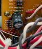
- Does the burned-looking area under the four resistors (R203-R206) on the sub power supply PCB mean that those are obvious candidates for replacement? Or does it mean that those are being fed something they can't handle from higher up in the chain? Those are each 3.3K and in parallel they measure 818 ohms, about like I'd expect.
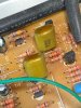
- The tops of these yellow caps on the power supply PCB look a little brown and "gooey". Is that anything to worry about?
I don't think I have grounding problems because the resistance from the ground point between the filter caps and the chassis ground = 0 ohms, as well as to the ground point on the main amp board (0 ohms). The end of every trace back to ground on the solder side of the PCB also measures ok.
I think I've finally figured out that the big black dot on the 4-ohm position of the switch on this PCB 10 4/8 switch diagram means we should assume that all the voltages on Schematic 2 should reflect the 4-ohm speaker setting.
Does the +B rail (highlighted in red) on Schematic 1 show as 51.2V because switch SW204 is in what looks like the 8-ohm position, since it's tapping the outermost windings of the transformer? Otherwise, how else could the same +B rail (also in red) on Schematic 2 now be 43.6V?
- Schematic 1
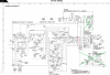
- Schematic 2

I don't think I can accurately gauge most of the measured voltages against Schematic 2 with what I'm currently getting if my rails are so different than the schematic.
If the rails voltages are not in spec, is that the very first thing to fix before anything else? If they're wrong, is it likely the be the filter caps or the bridge rectifier?
When I adjust the idling current by measuring the voltages across TP401/TP403 and TP402/TP404, which test point should get the - and + leads of the DVM? Does it matter?
I got a DROK/Mega328 transistor tester the other day that seems to work great. Can I test output transistors with that?
Am I overcomplicating things by not just swapping out Q441? Those output transistors aren't unobtanium, but they're not widely available, either. I believe I'd need to get a matched set of 4 of any particular type (2 per channel) if I replaced them. If an output transistor is bad and not just a rails problem from somewhere else, replacing it is of course a no-brainer. I just wanted to make sure some other component wasn't the cause.
I immediately hear the transformer when I power the idle amp on without the case and I'm near it. It's not loud, but it's there, humming. Is that normal?
Could a bad output transistor cause the rail voltages to be off?
Can I trust the service manual?
- There are typos in the Alignment Procedures. Clearly, the idling current adjustments are at VR403 and VR404, not VR401 and VR402.

- In the Alignment Procedures, should I set the speaker outputs to 4 ohms or 8 ohms for the initial DC Balance Adjustment step? I only ask because the manual doesn't say for that step, but it does specify 4 ohms for the final DC Balance Confirmation.
- Why are the Q401 and Q402 FET pins mislabeled on Schematic 2? I've triple-checked the datasheet for those parts against the traces on the PCB, and the Source and Drain are definitely in opposite places in real life compared to what's on the drawing.
- Because high current runs through this amp and it looks like high temperatures affect the solder joints, would it just be best to reflow all the remaining connections and see what I get? That seemed to help Q433 and Q429.
- I could re-cap the main board (or at least the electrolytics), which is probably a good idea and a good place to start, since the amp is 25-29 years old now, but I don't want to do shotgun troubleshooting.