• The move to the new server is done. There are some software and database maintenance updates in process. This has us passing the hat around to help out. We appreciate any donations. Seriously, even a dollar helps. The payment page may be found here - https://www.audiokarma.org/support.html

Harman kardon transistor identification

kaae

New Member
Hi' there
my old Harman kardon 630 twin, blew the fuses on left channel so i opened it up and found a couple of shorted transistors.
2rmwnd2.jpg

25ztncw.jpg


I tried looking up those numbers but nothing, they sat right after the fuses and transformers. not even in the circuit diagram was i able to locate which model number they had.

any help would be appreciated.

regard -

http://manuals.harman.com/hk/Service Manual/hk630 sm.pdf
 
Last edited:
Register to hide this ad
Those are not transistors. They are dual diodes. One is common anode and the other is common cathode. Used together for a bridged rectifier. Test them like diodes. If they check bad you can use two single 1N4007's for each diode package to accomplish the same function. AC rectification. Part number is 1850 and 1850R.
 
Last edited:
hopefully there are extra holes in the board to install 2 diodes for each dual diode . or you could of course replace with modern 3 leg ones .
as it happens i have a couple of new old stock ones i am saving for something that needs to look original .. maybe never use them as who leaves the cover off anyway ..:D
 
Last edited:
DO NOT use 1N400x diodes for this application. They are rated at 1 A. These diodes are the main rectifiers and much more than 1 A is required.

If there is no space to mount a 25 A or 35 A bridge someplace on the chassis and run wires back to the circuit board, then use something like 10A04 diodes, rated at 10 A average forward current.

http://www.digikey.com/product-detail/en/10A04-T/10A04-TDICT-ND/2242771

For mounting, insert short pieces of solid wire of the largest diameter that will fit in the circuit board holes, then bend that wire around the diode leads. Maintain space from the board.

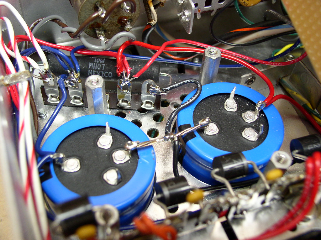
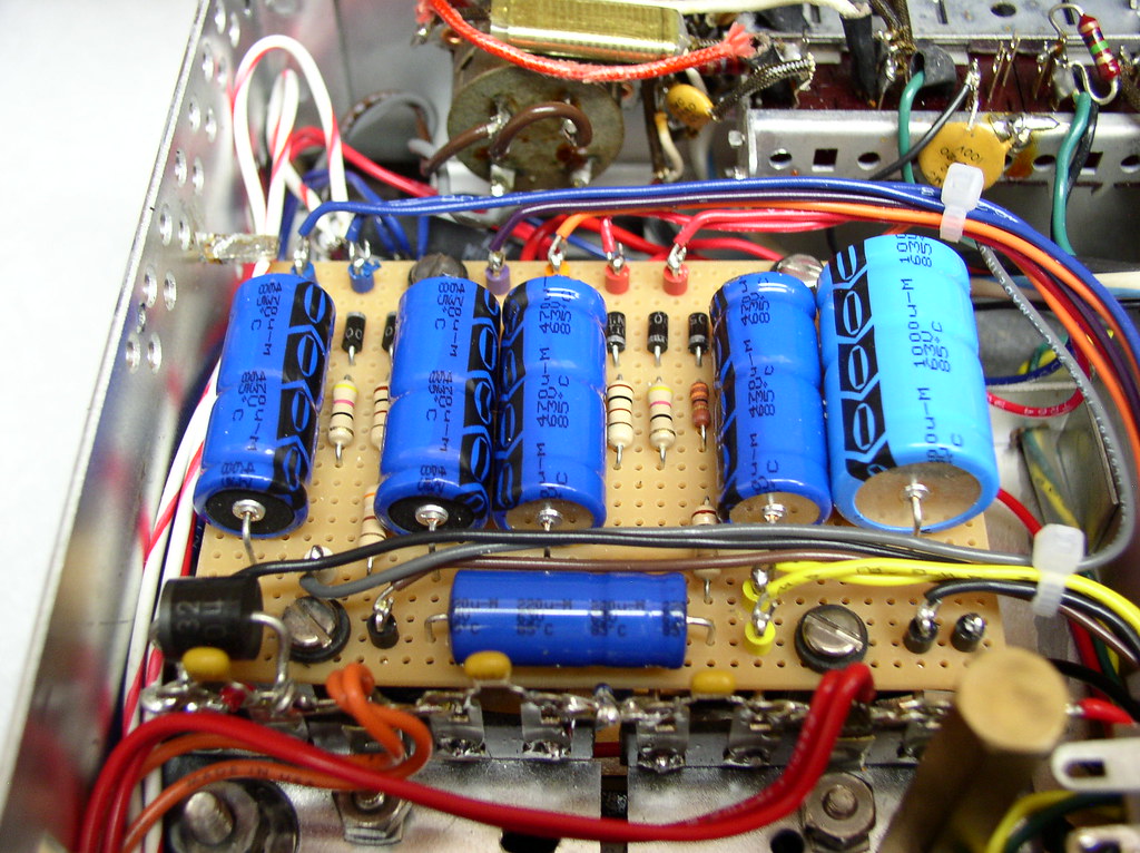
It would be better to mount a terminal strip for the diodes so that the leads can dissipate heat back to the terminal strip rather than a circuit board. This could have been the cause of the original failure.

Here is the setup on a vintage Fisher 600-T. In the first picture, the diodes are slightly out of focus at the front. In the second picture, the terminal strips and mounting are visible with one diode that had to be above the circuit board due to clearance. The other 3 diodes are under the board.

1414
12421069745_bfde0411fa_b.jpg

1415
12421552344_2d07109217_b.jpg
 
Back
Top Bottom