• The move to the new server is done. There are some software and database maintenance updates in process. This has us passing the hat around to help out. We appreciate any donations. Seriously, even a dollar helps. The payment page may be found here - https://www.audiokarma.org/support.html

Harmon Kardon 330b: Bias voltage locked in place.

HepGreg

Well-Known Member
Hey all;

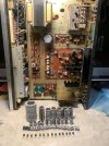
been working on an HK 330b for a few weeks. im in the home stretch, but ive run into an issue with the bias circuit. both channels seem to be locked in place at around 3.5mv. DC offset with a load attached is also right around 3.5mv. i thought maybe the pots on the amp board were bad, so i replaced them. but still they sit locked at ~3.5v. MV11 varistors measured good on both sides. the rest of the board has been rebuilt, mostly. anyone have any insights? Amp sounds good as is, but i would like to solve this last issue before putting the lid back on & calling it done.

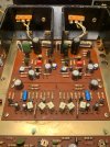
IMG_0821.jpegIMG_0820.jpeg
 
Register to hide this ad
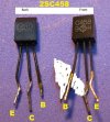
I see many 2sc458's that need to be replaced. They're on the top ten list of transistors that go bad.
May not resolve the bias problem but should be replaced.

https://audiokarma.org/forums/threa...ilure-prone-whatever-and-replacements.731653/

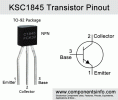
Mind the pinouts. I found ksc1845's are good replacements. When a 1845 doesn't work I'll try a ksc1815 which has the same pinout as the 1845.

View attachment 3845199View attachment 3845200
IMG_0769.jpeg

They have all already been replaced in pairs with HFE matched 1845s. The 1345s & 1509/777 pairs are still in the amp board. I didnt find a reason to replace them. The 458's spot in the circuit controls bias stabilization. It is stable currently, but wont adjust.

IMG_0823.jpeg
 
Last edited:
An open resistor somewhere? The mystery here is that both channels have the same problem. Defo replace the sc458s to see if it changes anything.
 
An open resistor somewhere? The mystery here is that both channels have the same problem. Defo replace the sc458s to see if it changes anything.
All 458s have been replaced. And yes, the bias issue is both channels. Super weird. I run into bias issues with 330s more than any other amps. Unless im somehow measuring across the wrong emitter resistors, but im pretty sure i measured the correct ones.
 
Oops, I should learn to read previous posts...

Anyhow, a measurement error comes to mind, but it shouldn't be that complicated. Check nearby resistors, on both channels, just in case.
I havent had any bias issues with my HKs, 330B included, so curious what might cause it.
 
Oops, I should learn to read previous posts...

Anyhow, a measurement error comes to mind, but it shouldn't be that complicated. Check nearby resistors, on both channels, just in case.
I havent had any bias issues with my HKs, 330B included, so curious what might cause it.

It's the left side emitters (looking topside) on each channel that need to be measured, correct? which resistors would you recommend checking first?

I measured the across the emitters (in circuit, which i know is not an accurate measurement) and they came in around 1.1k-1.2k ohms. Seems high, considering they're 0.47 ohms. But the rest of the circuit is probably adding to that.
 
Last edited:
Yes (if memory serves) left side emitter resistors are the measurement points for the bias. For checking resistors, any near the bias circuitry would be a good start.

However 1.1-1.2 kohms for the emitter resistors is awfully high. Did you mean ohms only? If they are in kilo-ohm range, they are toast, most likely.
 
Yes (if memory serves) left side emitter resistors are the measurement points for the bias. For checking resistors, any near the bias circuitry would be a good start.

However 1.1-1.2 kohms for the emitter resistors is awfully high. Did you mean ohms only? If they are in kilo-ohm range, they are toast, most likely.
Pretty sure it was Kohms, but in circuit. Ill pull them & take a proper measurement in a bit.
 
both channels seem to be locked in place at around 3.5mv.
Something is causing this to happen on both channels and the only thing they have in common is the main power rail and the power supply itself.

Did you check the bias before working on it and has anything been done to the power supply? If it still has the original main filter cap(s) installed, they and/or the rectifier diodes could be leaking and not allowing enough rail voltage to push the bias past the 3.5 mV showing on both channels.

I just reread your post and you say they are 'locked' at 3.5 mV. Does this mean you can't raise or lower the mV reading? At least the 3.5 mV DC offset on both channels indicates the amps are stable and that's a good sign.
 
Come to think of it, if emitter resistors were that bad, distortion would have been very obvious...
 
All 458s have been replaced. And yes, the bias issue is both channels. Super weird. I run into bias issues with 330s more than any other amps. Unless im somehow measuring across the wrong emitter resistors, but im pretty sure i measured the correct ones.

He's got one thing in common with both channels. Measuring method.

It's the 4 large sandcast resistors near the output transistors. Actually the manual says to measure the two on the negative side but I think you can measure all four. Should get a similar result.

You can measure the resistance of the output resistors in circuit. Should come out reading about what they are rated. If they are 1k you are either measuring the wrong resistors or they are blown..
 
Last edited:
Something is causing this to happen on both channels and the only thing they have in common is the main power rail and the power supply itself.

Did you check the bias before working on it and has anything been done to the power supply? If it still has the original main filter cap(s) installed, they and/or the rectifier diodes could be leaking and not allowing enough rail voltage to push the bias past the 3.5 mV showing on both channels.

I just reread your post and you say they are 'locked' at 3.5 mV. Does this mean you can't raise or lower the mV reading? At least the 3.5 mV DC offset on both channels indicates the amps are stable and that's a good sign.
Bias was at 3.5mv before rebuild. Yes, the voltage stays around 3.5-4mv. but it doesnt change when i adjust the bias pots. thought the old ones may have been shot, so i replaced them, and they are still locked around 3.5-4mv. Measured the old pots & they ended up still being good, but decided to leave the new ones in.
 
Last edited:
As noted the emitters will test in circuit, depending on your meter you should get about .6ohm (if they are .47). Importantly they should all be about equal.

Both channels same thing, and both locked before you started. Very strange, first guess would be measuring technique as not much else can make sense.

Can you post a pic of your meter hooked up and testing, a pic that shows where your leads are connected and the face of the meter?
 
high value emitter resistors would tend to show large amounts of voltage across them even at low current levels. It also wouldn't make any useful power output since the current that can flow in the output stage is pretty low.

Can you easily get a voltage measurement from base to emitter to see if changing the bias pot actually moves the voltage? Thats whats actually happening to affect current flow in the output stage. If no change, see if anything happens at the driver stage.

1790689773446.png
 
Maybe there's something wrong with the meter or its leads? Poor continuity would explain the measurements.
 
As noted the emitters will test in circuit, depending on your meter you should get about .6ohm (if they are .47). Importantly they should all be about equal.

Both channels same thing, and both locked before you started. Very strange, first guess would be measuring technique as not much else can make sense.

Can you post a pic of your meter hooked up and testing, a pic that shows where your leads are connected and the face of the meter?
I made some loops out of some cut leads & soldered them directly to the pads under the emitters on the trace side of the board. But i realized there are junction pins in the board that connect to one side & ground. Confirmed this by measuring both, same 3.5mv.

I will take some photos & measurements today.
 
Back
Top Bottom