Nick_the_'Nole
Super Member
Heh, quite the unholy royal bitch, wasn't it? 
So you have the thing working now?
So you have the thing working now?


Nick_the_'Nole said:Heh, quite the unholy royal bitch, wasn't it?
So you have the thing working now?

vwap said:Definitely a pain.
And apparently I didn't clean it well enough, it's beyond hope? Now it does the flickering at power-up, but then I hear a click, and then it stabilizes. There doesn't seem to be a repeatable length of wait between when I turn it from "Off" to an output. Is this normal? There is no loud static noise on the outputs, like there was before.
I suppose I could go back in and attempt to clean it again?
 Seems like parts of these things were just not designed for easy replacement, but I guess 25 or 30 years is a decent length of time for its first service call. The 5800 I just did had one lousy capacitor sitting on the tail end of the mainboard which barely protruded over the power supply board. I had to disassemble ten things just to desolder that one last cap. If they had moved it about a half inch over, I could have hit it from the bottom like all the rest of them.
Common problem on those pioneers. Pustelniakr has done this repair before and deoxit wont cut through burned contacts in the alps switch that is used.
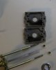
They are REAL contacts that can be disassembled (pita to get to tho) and burnished for like new performance for years to come.
I had a picture up, then took it down, of an sx-550 switch disassembled to show the contacts...
this is a link to the after action report on Rabbi Rich's work on that sx-450.
here is the picture again. I pulled it to save space here.


Yes yes, and I have done this many times, but some (a lot) have ANOTHER unused set of contacts. on the bottom, all we ever did was take it apart and move the unused contacts to the top.
Then things changed and they stopped putting in the other pair of contacts, big let down.