• The move to the new server is done. There are some software and database maintenance updates in process. This has us passing the hat around to help out. We appreciate any donations. Seriously, even a dollar helps. The payment page may be found here - https://www.audiokarma.org/support.html

Having trouble finding oscillation/bias problem - where do I look?

As you stated , the motor-boating could be present before your repair, since you didn't test the phono preamp before...

If you determine that the problem is coming from the phono preamp, I suggest a recap of that board first.

Try to check if the rest of the functions are OK and just the phono has the problem. Try shorting the RCA input too, to see if the problem persists.

Some receivers have a "REC OUT" or "TAPE OUT" section that you can send to a second amp, a headphones amp, or a tape recorder, and check if the noise is present there too. That output is usually before the tone controls, so recording level doesn't change when you move the volume knob or the tone controls.

This will help to isolate the problem.
 
Well, nuts. Egg on my face. I made another mistake of assuming since I only heard the noise by switching to phono and aux with no signal that it must be the pre amp. Once the receiver was split i could plug my Kindle into the power amp and no noise, right? Wrong! And if the noise was the preamp it would be heard in whatever amp the preamp was then connected to. Wrong! I followed my own advice to check every thing and found the noise - oscillation-motorboating - whatever , IS originating in the power amp. With the power amp disconnected from the preamp and no other input signal, I turned up the volume and bass and there was the noise and the speaker flop. And the amp started to heat up quickly in the right channel just like before. The pre amp was fine when connected to another amp.

Now I'm checking all the new caps again for the umpteenth time. It has to be somewhere, right? The problem was there before I swapped semis, and I doubt the amp would have worked so well if pin outs were inverted. Let me think on it some more...

The receiver went down with an open speaker relay.
Voltage checks found weak and confusing values on the relay.
Flyback diode on the relay was changed and the relay closed normally.
Amp sounded good with FM, (low volume so as not to wake the wife.) Figured the problem was fixed.
Changed all electrolytics on the Audio and Power Supply boards.
Amp sounded good with FM. I let it run. (DC offset was below 10mv in both channels. great!)
I wanted to warm it up to set the bias, so I was checking bias every 10 minutes or so.
Amp started to overheat into 3-way 12's when cranking pretty good. I wasn't surprised, it ran several minutes pretty loud.
Bias readings were very high on the hot side (right), so I shut it down. Bias returned to normal range when cool.
I was using the old crappy (original) bias trimmers, so I installed new Bourns multi turns and new bias circuit transistors.
Bias adjusted correctly with the new parts. Cleaned it all up and was checking the phono - empty, no signal - when I saw the speaker pop in and out in rhythm.
Wub-wub -wub increases speed with more volume or more bass. Right Output heats up quickly, or at least faster than the Left. No noise in the Left.
Problem is in the power amp, and not noticed until after installing new caps.
Voltages I can compare to s/m specs seem to check out OK on Audio and PS boards. Until it heats up, of course, then bias v. shoots through the roof.

Back to the drawing board! (This ever happen to you?)
 
Bad solder joint or transistor going into thermal runaway, check the joints if all ok and if no test equipment try swapping transistors from bad to good channel one area time, starting with the input pair first, it will be time consuming bit should find the issue
 
Last edited:
With the amp disconnected from the preamp raising the volume should have no effect! I still think the problem is in the preamp or power supply. Something in the preamp is driving the power amp hard, causing the power supply to modulate, which feeds back to the preamp, causing more signal to the amp. This IS motorboating.
You need a scope to fix this. Otherwise you will not be able to tell what is happening or where it is coming from.
Here is one thing you can try to determine what may be happening.
1. Disconnect your speakers so there is no load on the amp. Leave the preamp disconnected.
2. Connect your meter to the bias terminals and monitor the bias.
3. Put the receiver in AUX and raise the volume. Does the bias go up?
4. If the bias does not go up, connect your meter to the speaker output on one channel and raise the volume. Does the DC offset go up? If not, try the other channel.
5. If the DC offset does not go up, connect the preamp and repeat steps 2 - 4.
If the Bias stays stable and the DC offset does not go up, you need an oscilloscope to check the supplies to see if they are moving around when the amp draws current. Also check ground connections. Using your meter, with the power off, check continuity from power supply ground at the 2 main caps to chassis ground. Then check chassis ground to every point on the amp and preamp and phono boards that is supposed to be ground. An open ground can cause motorboating, and the supply voltages will be good.
The reason the preamp works ok with an external power amp is because the external amp does not share ground or power supply with the preamp. When the external amp draws more current it can't affect the preamp power supply.
 
I also want to add that if you are working on something with a separate power amp and preamp and the amp seems ok when they are disconnected, connecting the preamp to another power amp is a very bad idea. You could have damaged the other amp. You were lucky this time.
 
A cap installed backwards will heat up at least. Or explode if the voltage is high.

Swapping parts from a working channel to a non working one is not a good idea. You can end with 2 non working channels.

How do you check transistor pinout? I've seen several that don't match the datasheet. Different pinout from different manufacturers with the same transistor number.
 
How are you separating pre and main? There is no main/pre connection in this amp.
If you are using the 4 channel adapter in the back, the output is fixed level, and the input is before the volume and tone controls, which all makes sense. This problem may be tricky to solve, as the tone controls are in the feedback circuit of the power amp, not easily separable. Most likely a cap, but could be bad or dirty tone control pot, or bad solder. Start with a good cleaning of bass and treble controls, then careful inspection of the caps in the tone control circuit.

As a comment - Kenwood used two 3.3 electrolytics back to back in the tone amp. If it fits, I would use a 1.5 film cap with a .15 film in parallel instead of the two elctrolytics in series.
 
Wow, thanks for all the comments! I'm still learning how to run this chat board, so bear with me if it gets tedious.

With the amp disconnected from the preamp raising the volume should have no effect!
Typically true, dr, but not the case in this amp, the tone and volume controls are on the Audio board with the outputs. I'll try to post the schematic, but i was having trouble with size and formatting. Please read my long winded report on page one.

I also note there could be trouble sticking this preamp into another amp, so I used a small mixer in between, and used a tiny toy computer sound amp. I had success, the preamp worked OK using the Aux input. There was no wup-wup in the phonos 1,2.

[How are you separating pre and main? There is no main/pre connection in this amp.]
There are preamp out/power amp in RCA jacks on the back panel of the KR-5600. There are shunts between them. I have run them through a graphic eq before. They do not show up on the schematic though. If you can view the schematic, notice the pre amp is two IC's and little else.

Thanks for the guidance, dr audio. I have been monitoring bias as the temp increased, and it went very high, (which I quickly shut down!) maybe in the hundreds of mv? I shut down in a panic when I found it. I can retry under control and report the results. DC offset has been superb, under 10mv on both channels. Thanks for the tips on checking ground continuity too, I sure will!

No bad caps to report, nothing smoked. Did not find caps inverted after four or five times through the board. Wish I did and that was it!

enaldo, I had not changed any transistors before I found the problem. I changed 4 transistors in response to the problem, and some diodes too. The transistors were common c945's and a733's, widely used and reported in AK, and sourced through Mouser. I checked pinouts with a cheap chinese semi tester, comparing them to the originals. I also checked in data sheets, in AK, and they were etched on the pcb. There were no changes noticed after the swap.

edit - I used the recommended a733C and c945C types with the center collector to drop right in.

sregor - this circuit has the two 3.3's, but I had already changed them to Nichicon PW's. I did use .47 film caps on the inputs . There are also some non-polarized electrolytics (is that an oxymoron?) on the board.

The Audio board makes the noise and oscillates by itself, separate from the pre amp. When it is cold, every voltage I have checked seemd well within normal limits. I mean 39v for a 38.5 b+ rail, 14.2v for a 14.1v spec, .68v for a .75spec. Nothing crazy. I'm taking measure of the diff pair, pre divers and bias trannies now. Hope to find it there!

Thanks so much for the discussion! Y'all are great! Now, how do I post the schematic?

 
Last edited:
Can you please clarify whether the 'wup-wup-wup'/noise is present on both channels or just the right?

If both channels are exhibiting the issue, it's likely the power supply rails are being modulated and/or it's a grounding issue. There's a 14V zener which is common to both channels to run the differential pairs. As the problem occurs when it heats up, it's quite possible this zener could be a possible cause. The caps are connected to the anode of the zener and grounded. Check this ground is of a low impedance. Also, you need to monitor the rail/reg voltages when the problem occurs.

Also, the adaptor in/out links you are referring to, are not preamp outputs/power amp inputs. They are just the same as a non selectable tape loop. Designed for a line level processor- eg a graphic eq or 4 channel processor. The in/out loops are before the balance, volume tone and output stage. The 5600 doesn't have a preamplifier (other than the RIAA stage) as such, it is a high gain power amp with the tone stage in the feedback loop.

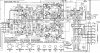
Relevant discussed part of 5600 schematic:

5600 sch.JPG
 
Last edited:
Would you take some time to build a probe to use a computer software oscilloscope?

There is a free software, "visual analyzer" (no affiliation) that will turn your computer into an oscilloscope, signal generator, spectrum analyzer and more.

Perhaps you invest some hours learning the basics, and then you can find this fail .

The basic oscilloscope function is just turn it ON, connect the probe to the sound card, and watch the uncalibrated signal on the screen. To take measurements you need to calibrate signal levels. But not needed to see a signal shape.

Just an idea.
 
Last edited:
Can you please clarify whether the 'wup-wup-wup'/noise is present on both channels or just the right?
Thank you r-john for the excellent comments and your help with posting the schematic. Yes, just the right channel.

I first noticed the slow cycling while trying to set the bias after recapping the PS boards and the Audio board (this one). I used the old bias trimmers. After I found the heat and the very high bias on the right channel I responded by changing that zener, the bias transistors, and the trimmers. I used previous threads in AK for this knowledge. After the changes, the cycling remained. I could adjust the bias just fine. The amp holds voltages when cold at 0 volume, but when Volume and Bass go up, the cycling wup-wup starts and increases speed with higher volume or bass settings. I don't have a scope.

f both channels are exhibiting the issue, it's likely the power supply rails are being modulated and/or it's a grounding issue. There's a 14V zener which is common to both channels to run the differential pairs. As the problem occurs when it heats up, it's quite possible this zener could be a possible cause. The caps are connected to the anode of the zener and grounded. Check this ground is of a low impedance. Also, you need to monitor the rail/reg voltages when the problem occurs.

As noted, the first thing I changed was the zener Dm7. I tried checking grounds all over the board and where I could reach on the PS boards, and the DMM chirped instantly every time. What is the way to check for low impedance as you suggest? Treat the connections like a big resistor? with an ohm setting? I will fire it back up to check the rails. Cold they read 39 and -38.9 for the 38.5 spec.

Also, the adaptor in/out links you are referring to, are not preamp outputs/power amp inputs. They are just the same as a non selectable tape loop. Designed for a line level processor- eg a graphic eq or 4 channel processor. The in/out loops are before the balance, volume tone and output stage. The 5600 doesn't have a preamplifier (other than the RIAA stage) as such, it is a high gain power amp with the tone stage in the feedback loop.

Thank you for clarifying this. I tried to explain what I knew by reading in AK and my previous work on tube amps for guitars. The S/M calls it the pre amp.

Can i check the feedback loop more carefully? I need help to understand where this is exactly. My guesses have not been too bad so far, but I'm not an EE and I want to learn this better. Thank you so much for your assistance!
 
Hello elnaldo! Just happened to be here. I think that's a great idea and I would build something. Thank you! Do you have a link?
 
Just Google visual analyzer. (Sillanum software or something. No affiliation)

The probe must be isolated from the DC with a capacitor. I'D use 1uf 250v film cap. There are more sophisticated probes, with 10x attenuation or zeners to protect the sound card. Just Google "using your pc as oscilloscope" and you'll find all what you need.
 
Please be careful and ask here before burning your sound card . I burned mine years ago. No sound in my laptop :(
 
Excellent, found it. Visual analyzer. I expect the program details the probe instructions? Because I am new to this I do find myself to be overly cautious and redundant.
 
VA is a great little piece of software, however you need to be very careful or you will destroy your soundcard front end. Your soundcard will probably take about around 1.2-2.0v maximum before overload. You have voltages 20x higher or more than that in the amp stage.

It would be a good idea to use a cheap USB sound card available for a few dollars instead of the internal sound card on your PC/Notebook as the inevitable mistake is less costly...

You'll need to make something like this:

http://levysounddesign.blogspot.com.au/2014/12/usb-soundcard-oscilloscope.html

Also, make sure you wind up the sampling frequency to at least 96K or you will have a brickwalled FFT at lower sampling rates that will miss HF oscillation.
 
Last edited:
Ha ha, I was doing fine until you said "you will have brickwalled FFT at lower sampling rates that will miss HF oscillation" and I truly had NO clue about what you meant. I have never used a scope, it was just that several folks thought I needed one to find this problem. So sorry, I don't know the lingo yet, so it kind of struck me funny. (Maybe it's French?) Well, glad we can enjoy a problem puzzle, right?

I'm working on finding voltages that change with the boost in bass or volume. Haven't had time to get far, though, the wife had Saturday errands for me. I'll try to post later what I learn tonight.

Thanks again for your kind help and making me smile to break the frustration! And thanks r-john for helping me understand the in/out break. I will include some voltage readings from the preamp too.
 
What you can see with the pc oscilloscope is only AC , ripple and sound signals. High DC voltages are blocked by a capacitor. You can build a "10x" voltage divider at the probe so you are sure you won't exceed a couple of volts, or even 2 small zener back to back.

But if you don't measure the power amp output, signal voltages should be safe.

Anyway those cheap USB sound cards are OK. That's what I use after burning the internal sound card.
 
If the amp is HF oscillating at a high level and the sample rate is too low (ie 44.1), the bandwidth on the oscilloscope or FFT screen will only be 22K (half the sampling freq) so he may not see anything. That can easily take out the soundcard. Two small zeners won't save it in that case. That's why I suggest 96K or above and 24 bit if his card will do it.

We know for sure that output transistor/s are being turned on hard in a fault condition as the channel gets hot fast, so we've got higher than quiescent voltage levels in the feedback loop also. Not a time to be poking around with a dubiously protected front end IMO.
 
If the amp is HF oscillating at a high level and the sample rate is too low (ie 44.1), the bandwidth on the oscilloscope or FFT screen will only be 22K (half the sampling freq) so he may not see anything. That can easily take out the soundcard. Two small zeners won't save it in that case. That's why I suggest 96K or above and 24 bit if his card will do it.

We know for sure that output transistor/s are being turned on hard in a fault condition as the channel gets hot fast, so we've got higher than quiescent voltage levels in the feedback loop also. Not a time to be poking around with a dubiously protected front end IMO.
This is correct. To see oscillation at high frequency you need an oscilloscope, preferably with a bandwidth of at least 20MHz. Most likely the oscillation will be at 10MHz or less in an amp with normal output transistors.
 
Back
Top Bottom