
• The move to the new server is done. There are some software and database maintenance updates in process. This has us passing the hat around to help out. We appreciate any donations. Seriously, even a dollar helps. The payment page may be found here - https://www.audiokarma.org/support.html

Head shell Wires

JimmyEJames

Super Member
Be careful when research any thing on internet
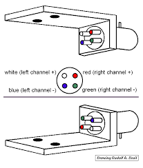
This guy is NOT showing correct standard SME convention
I know there are a few MANUFACTURER specific exceptions but this is bad information most of time
I email him
If you new to this and need pattern DO NOT USE THIS
http://www.petervis.com/record_players_and_turntables/headshell_wiring/headshell_wiring.html

This is CORRECT for almost all machines and almost any thing made in Japan
Just noticed thought to share
JJ
images
 
Register to hide this ad
Be careful when research any thing on internet
This guy is NOT showing correct standard SME convention
I know there are a few MANUFACTURER specific exceptions but this is bad information most of time
I email him
If you new to this and need pattern DO NOT USE THIS
http://www.petervis.com/record_players_and_turntables/headshell_wiring/headshell_wiring.html

This is CORRECT for almost all machines and almost any thing made in Japan
Just noticed thought to share
JJ
images

JJ, your English is a little rough on the edges, but I certainly understand your point. Here is something I find interesting, that the wires colors on the headshell do not correspond to the colors on the cartridge, they switch from outside to inside. Not sure why they did that, but that is the way it is. I'm looking at a Technics headshell right now and on the outside (outer rim of platter side), the headshell has the red (+) and green (-), but the cartridge is showing the white (+) and blue (-).

Go figure that one out.

Wayner
 
JJ, your English is a little rough on the edges, but I certainly understand your point. Here is something I find interesting, that the wires colors on the headshell do not correspond to the colors on the cartridge, they switch from outside to inside. Not sure why they did that, but that is the way it is. I'm looking at a Technics headshell right now and on the outside (outer rim of platter side), the headshell has the red (+) and green (-), but the cartridge is showing the white (+) and blue (-).

Go figure that one out.

Wayner
No standard for cartridges sometimes even from same maker but I have never had one was not marked
Main reason SME became de facto wiring standard and all more reason to be diligent
But use Shure as example almost always have colors facilitate correct install
SME convention if I guess on 99% of machines
That is reason for posting guy did no good service but LOT of effort with photographs and text to tell backwards story!
JJ
 
Well Jimmy, when Thorens first did this, there was no SME to comply with, so they just did their thing regardless. ;)
His is not correct for Thorens either so what is point?
Germans Swiss do something different from British?
And why I am not surprised?
Point was not to debate or look for anomalies I say there were EXCEPTIONS by some manufacturer
Thorens is one of those
But I guarantee you Thorens end cables will match correct channels on amp
Guy with website just wrong so do not use if new to this
That was ONLY point
JJ
 
It's just an obscured web site and his wiring standard is not the only thing that's wrong with it. Have you seen how he spreads the wires so they're much lower than the cart?
google must like his pictures! ; - )
I not waste time checking him out after see that article! ; - )
JJ
 
i think he did say the signals dont mind which colours are on the wires so long as you put them in the right places .
That is point he puts them in WRONG places
Channel orientation will NOT be correct unless person KNOWS to reverse cables at amp
And that person will not be looking for head shell wiring convention!
His article WRONG for SME WRONG for Thorens
How difficult can this be it includes pictures!
That was point of post to steer clear any new person may be looking for this information
Do NOT refer to that guys material it erroneous and he at top of pop with basic search
No point to make here no debate INFORMATIONAL
Simple
JJ
 
Many different, influential organizations such as the RIAA have tried to institutionalize standards to make these kinds of problems go away with some success. As an example, all cartridge manufacturers use the 1/2" cartridge mounting standard, but after that, I have no idea. Sometimes, the wiring problem is in how you view the cartridge (from the front or from the back as an example). Why the location of the wires flip from the outside to the inside is beyond my comprehension. I have no understanding why it came about, but it is a reality that all of us have to deal with. You just have to pay attention to what your working on.

'ner
 
Many different, influential organizations such as the RIAA have tried to institutionalize standards to make these kinds of problems go away with some success. As an example, all cartridge manufacturers use the 1/2" cartridge mounting standard, but after that, I have no idea. Sometimes, the wiring problem is in how you view the cartridge (from the front or from the back as an example). Why the location of the wires flip from the outside to the inside is beyond my comprehension. I have no understanding why it came about, but it is a reality that all of us have to deal with. You just have to pay attention to what your working on.

'ner
Read it even better LOOK at it all will be revealed!
You can see what he did
The guy says in article if you read he wants every thing to be straight across with no wires crossing
Meaning he wants pin looking at other pin to be connected in straight line
Only reason it as close as it is because cartridge he used just happens to be inverted SME when mounted to shell
He thinks they aligned by design! ; - )
No need to get COMPLEX! ; - )
JJ

His words
"On the opposite side there are four pins coming out of the H-4 bayonet mount. These four pins align with the opposite four pins on the cartridge. All you need is a small length of wire to connect each pin to the opposing counterpart pin on the cartridge. It is that simple! There is no need to cross over the pins or any complex mapping. Each pin from the bayonet coupling connects straight to the opposite pin on the cartridge.

If you know that each pin connects straight to the opposing pin then you can pretty much forget the wiring colour code because electrons do not care which colour wire they travel through, as long as your pins connect correctly"
 
Well then his music will be inverted, with the left channel on the right side and the right channel music on the left side. This is a form of distortion (defined by the fact that it was not like the original).
 
All interesting stuff and good information. I'm currently looking at rewiring the headshell on my Labcraft Type 605. The original wires were looking stuffed and the connectors were in poor condition. Unfortunately the original wires were also just plain clear covered copper and had no colour coding, making connecting a cartridge a bit hit and miss. I want to attach new coloured wires, which I will have to solder onto the headshell pins. It looks like an exercise in patience to me!

However, my problem is how to determine which wire goes where. I'm guessing there was no convention for wiring in 1962! Any tips on how to determine what the pins are so I can solder the correct wires on? I have a multimeter and a very basic knowledge of how it works.

IMG_2279.JPG IMG_2278.JPGfullsizeoutput_4fb.jpeg
 

Attachments

  • IMG_2215.JPG
    IMG_2215.JPG
    31.3 KB · Views: 11
Last edited:
Ha, not to worry, it was easy enough to just check the continuity to the RCA cables to work out the polarities of each pin. Now I just need a swig of whisky to steady my hands for the soldering job :)
 
Back
Top Bottom