
You are using an out of date browser. It may not display this or other websites correctly.
You should upgrade or use an alternative browser.
You should upgrade or use an alternative browser.


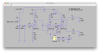
Ok, I became convinced to go back to the 5-20 style front end with 6CG7 everywhere, and again over lunch, I think I got the operating point of the AF amp and PI squared away. With -14dB of feedback, on paper it hits 500mVrms input sensitivity, which is pretty darn close to my target.
Attachments
Inspired by @kward's adventures with the Heath 51-58 output transformer, I was motivated to go back and fiddle with this shelved-for-now project. I took some cues from Kevin's work to get the feedback loop stable on his amplifier, and also changed the screen and bias supply to be more like @dcgillespie's universal EFB(tm); that is to say, I scrapped the Zener string, LR8N, and TIP50 in favor of a voltage divider and STF16N50M2 MOSFET. However, this design still uses Dave's cathode regulator circuit rather than a negative bias supply (this is done to get the voltage drop across the EL84Ms within max ratings).
I'm toying with the idea of using a CCS as the plate load on the gain stage ... I plan to throw together a simulation of that front-end to see how much tweaking (if any) of the inverter stage will be necessary. 2ma is right on the edge of what the IXYS 10M45 can regulate, so a higher supply voltage to the gain stage (with a correspondingly higher current through the 6CG7) might be necessary. If I need extra voltage drop across the inverter, I still have a 50Vac tap on the power transformer that's currently unused, which could be recruited to provide a negative rail.
I'm toying with the idea of using a CCS as the plate load on the gain stage ... I plan to throw together a simulation of that front-end to see how much tweaking (if any) of the inverter stage will be necessary. 2ma is right on the edge of what the IXYS 10M45 can regulate, so a higher supply voltage to the gain stage (with a correspondingly higher current through the 6CG7) might be necessary. If I need extra voltage drop across the inverter, I still have a 50Vac tap on the power transformer that's currently unused, which could be recruited to provide a negative rail.
Attachments
Last edited:

BinaryMike
Pelagic EE
Do you need more than 1V sensitivity, or do you want more GNFB? You could get more gain from this circuit pretty easily without going to a CCS.I'm toying with the idea of using a CCS as the plate load on the gain stage ... I plan to throw together a simulation of that front-end to see how much tweaking (if any) of the inverter stage will be necessary. 2ma is right on the edge of what the IXYS 10M45 can regulate, so a higher supply voltage to the gain stage (with a correspondingly higher current through the 6CG7) might be necessary. If I need extra voltage drop across the inverter, I still have a 50Vac tap on the power transformer that's currently unused, which could be recruited to provide a negative rail.
Do you need more than 1V sensitivity, or do you want more GNFB? You could get more gain from this circuit pretty easily without going to a CCS.
I don't really need additional sensitivity. I know I could increase the gain to almost what I could get with a CCS by either using LED biasing or by splitting the cathode bias resistor and bypassing the top leg (and adjusting the feedback resistor as necessary). I was mainly intrigued by what improvements in distortion might be had with a CCS load, although I already expect distortion to be very low any way due to the local feedback from the un-bypassed bias resistor... and then -20dB of feedback is going to drive what remains into the dirt.
I've been itching to build something again, but I'm still in a lack-of-shop-space situation right now... I plan to build this amplifier on a turret board, so instead of tinkering with the circuit any further, maybe I'll start planning the layout of the board.


Well, I had a long international flight to suffer through yesterday, so I spent some time putting together a simulation of the front-end. I'm glad I did, because I quickly realized that I totally botched the first voltage gain stage ... I went back and looked at the load line I drew for it and though to myself -- "What the hell were you thinking??" It was obviously wrong.
The nice thing, though, is that the fix actually simplifies the power supply, because I feed the gain stage with the same +315V that I feed the inverter stage with. And with a slight change to the cathode bias resistor, the voltages simulate dead-on for ideal DC-coupling to the inverter (and they cross-check correctly against a not-obviously-wrong load line).
The nice thing, though, is that the fix actually simplifies the power supply, because I feed the gain stage with the same +315V that I feed the inverter stage with. And with a slight change to the cathode bias resistor, the voltages simulate dead-on for ideal DC-coupling to the inverter (and they cross-check correctly against a not-obviously-wrong load line).
Attachments
Watching with great interest. I have an AA100 donner but I am using 807 tubes.
With 807 you're going to need more front-end gain in order to drive them to full power, I think. Probably want to use a 12AX7 for the gain stage rather than the 6CG7 / 6SN7 that I'm using for the EL84M output stage.

The original Williamson amps stateside ran a pair of 6SN7 in the front end driving an 807. It was a voltage amp direct coupled into the phase inverter, and the second tube worked as a second voltage amp after the inverter stage.
Right, the LTP style inverter has 1/2 the gain of a regular gain stage... So the 5-20 front-end is "full-gain x half-gain", whereas the Williamson would be "full-gain x unity x full-gain".

On my 1625 amp (807 tube, but 12V heater) I originally ran a 6DJ8 gain stage direct coupled to a 6FQ7 cathode coupled differential pair. It had enough gain when used as a straight power amp, even after 12 to 15 dB feedback applied. But I changed the 6DJ8 out for a 12AX7, and then applied 18 dB feedback, only because it was to be used in an "integrated" amp fashion, meaning no preamp, just driven directly by a frontend digital source. As I recall in that mode, sensitivity was 0.5V or right near there.
Been dabbling with this a bit more... decided to sketch the layout, and had trouble physically fitting the choke I had selected. That, combined with other recent AK threads about power supply strategies prodded me to do better...
This version of the schematic does away with the vacuum rectifier and employs a Zener + MOSFET regulated B+ supply (in addition to the MOSFET-regulated screen supply and the EFB cathode regulator). Even at full power, simulation shows the B+ sagging only a couple of volts (mainly due to the caps failing to keep up).
3 beefy JJ caps (800uF + 800uF + 500uF) take their place on the deck, rather than a 2-section cap + the 5AR4. The 740VCT transformer necessities 1.4kV-rated rectifier diodes.
I still need to find a spot to stash the B+ supply board ... but that's going to be a lot easier than the choke.
(Apologies -- the schematic doesn't have the appropriate symbol for a Zener ... I thought I had a template for that in the drawing program I use, but I guess not? ¯\_(ツ)_/¯ )
This version of the schematic does away with the vacuum rectifier and employs a Zener + MOSFET regulated B+ supply (in addition to the MOSFET-regulated screen supply and the EFB cathode regulator). Even at full power, simulation shows the B+ sagging only a couple of volts (mainly due to the caps failing to keep up).
3 beefy JJ caps (800uF + 800uF + 500uF) take their place on the deck, rather than a 2-section cap + the 5AR4. The 740VCT transformer necessities 1.4kV-rated rectifier diodes.
I still need to find a spot to stash the B+ supply board ... but that's going to be a lot easier than the choke.
(Apologies -- the schematic doesn't have the appropriate symbol for a Zener ... I thought I had a template for that in the drawing program I use, but I guess not? ¯\_(ツ)_/¯ )
Attachments
It provides some controlled current flow to charge the cap at the first MOSFET gate (to provide a soft-start effect), and it's also part of the ripple filter. I took this cue from another schematic I saw, and toyed around with eliminating it, but this version performed the best (in simulation) of all of my attempts. I'll admit my mojo with current-controlled devices is not quite up to snuff...
Hm, I just realized, there is a mistake in this... I'm exceeding Veb on the PNP. Attached is a correction, which necessitated another small tweak (in the Zener chain).
Hm, I just realized, there is a mistake in this... I'm exceeding Veb on the PNP. Attached is a correction, which necessitated another small tweak (in the Zener chain).
Attachments
I see you are unabashedly using silicon to enhance the performance of your amp. Maybe we should call it the "bionic amp"
It is hereby dubbed "The Steve Austin".