• The move to the new server is done. There are some software and database maintenance updates in process. This has us passing the hat around to help out. We appreciate any donations. Seriously, even a dollar helps. The payment page may be found here - https://www.audiokarma.org/support.html

Heathkit AA-40 - strange voltages at 6AN8A plates

david winter

Classical music lover.
Hi,

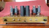
I have been working on a Heathkit AA-40 amp for which I did the following works:
- Set to 230V mode (powered at 240Vac).
- Surgistor replaced with CL-90 varistor
- Tubes: two NOS Sylvania 6AN8A + four good EL34
- All electrolytics and coupling caps replaced
- Most resistors replaced (out of tolerance)
- Pots cleaned
- Balance / Bias set as per manual (stable)

Due to the 240V mains, the plate and screen voltages of the EL34 reach 520V.
Grid voltages are -43V on three EL34 and -48V on the last, with both balance/bias set as per manual.
Right now I didn't bother putting a matched quad of EL34 so I used a pair of JJ (testing at 80mA each) and a pair of Philips/RTC testing at 90mA/100mA (NOS = 100mA at 250 / 250 / -13.5).

What I can't understand is some insufficient voltage at both pentode plates (pins 6) of the 6AN8A: 60V and 85V instead of the 120V as indicated on the schematic.
Screen voltages are ok (36V vs 40V on schematic) as well as the cathode voltages (0.9V and 1V vs 0.8V on schematic).

I double checked both 6AN8A on each section with my Metrix tube tester and they output at least the NOS specs.

Any ideas ? Thanks in advance.
 
Register to hide this ad
How about the 330K pentode plate resistors and the 10K 2W resistor in the power supply providing voltage to the node powering both driver tube plates? If the pentode plate resistors go high in value, the screens would take up the slack so that the cathode voltage would appear relatively normal.

Dave
 
How about the 330K pentode plate resistors and the 10K 2W resistor in the power supply providing voltage to the node powering both driver tube plates? If the pentode plate resistors go high in value, the screens would take up the slack so that the cathode voltage would appear relatively normal.

Dave

I thought about that but the 10K is new and both 330K measure 338K so close enough IMO.
For the sake of closer values I replaced the 820K and both 330K which tested good.
The screen voltage of the 6AN8A is 40V, and still have the same trouble at the pentode plates.
Voltage before the 330K is 400V.
 
what sort of meter are you measuring this with? I'm going to guess the originals were measured with a VTVM, but it should specify on the schematic. Those typically had a 11M input impedance. A decent digital at 10M will read essentially the same but if you are using an analog meter with 20k/ volt loading it might be enough to throw it off when read through a 330k resistor.
 
Hi,

I have been working on a Heathkit AA-40 amp for which I did the following works:
- Set to 230V mode (powered at 240Vac).
- Surgistor replaced with CL-90 varistor
- Tubes: two NOS Sylvania 6AN8A + four good EL34
- All electrolytics and coupling caps replaced
- Most resistors replaced (out of tolerance)
- Pots cleaned
- Balance / Bias set as per manual (stable)

Due to the 240V mains, the plate and screen voltages of the EL34 reach 520V.
Grid voltages are -43V on three EL34 and -48V on the last, with both balance/bias set as per manual.
Right now I didn't bother putting a matched quad of EL34 so I used a pair of JJ (testing at 80mA each) and a pair of Philips/RTC testing at 90mA/100mA (NOS = 100mA at 250 / 250 / -13.5).

What I can't understand is some insufficient voltage at both pentode plates (pins 6) of the 6AN8A: 60V and 85V instead of the 120V as indicated on the schematic.
Screen voltages are ok (36V vs 40V on schematic) as well as the cathode voltages (0.9V and 1V vs 0.8V on schematic).

I double checked both 6AN8A on each section with my Metrix tube tester and they output at least the NOS specs.

Any ideas ? Thanks in advance.
Was the voltages in range before you "worked" on it ?
 
for those who've not seen this amp, like me. It is a great amp and worthy of a rebuild and better input and speaker connects.

Screenshot 2022-10-20 143540.png Screenshot 2022-10-20 143513.png
 
Beautiful piece! I've got one that I've just never gotten around to restoring yet. It's minus the cage, so I would love dearly to find one.......

Hope you find your issue. I was going to suggest that your meter might be loading the actual plate voltage potential down as well -- but when you indicated that the screen voltage was correct, I dismissed the thought. But the screen grids have a large decoupling cap connected to them (20 uF) that could potentially hold their reading in place during a short measurement check if the meter was trying to load the voltage down -- where as the plates (of course) have no such storage cap connected to them. Therefore, they would react instantly to the meter load, where as the screen grids would not. To see if the meter is loading the circuit, one test you might make is to connect the meter to the screen grid circuit and just let it hang there for a few minutes. If it starts dropping notably after a short period, then you have your answer.

Dave
 
Last edited:
Thanks for your suggestions. I've been working on tube amps for almost two decades without such trouble, but I'll do the test anyway (eventually using a smaller decoupling cap).
I'll also use another DMM (Metrix or Fluke) to compare, although I never had that issue with my usual DMM before.
I replaced the 330K and 820K resistors for the sake of being closer. Negligible change (of course).
My unit isn't as nice as the one pictured as it's been staying in a storage for a long time, but at least it works despite a different gain between channels (reminder: 6AN8A are both NOS and test new, and EL34 are used but output around 80mA each).
All resistdors left in place are within tolerances. Will post with further test results. Thanks again.
 
I did another test with another (Fluke) DMM: same problem with and without the 20µF cap.
With the cap in place I have 88V (Channel A) and 48.5V (channel B) and the plates. Both voltages constantly vary of +/- 100mV.
I double checked (again) all resistor values and wiring around the 6AN8A but everything is fine.

There's also some voltage drop around the triode section of both 6N8A:
Pin 1: 310V and 312V (320V on schematic)
Pin 2: 64V and 63V (100V on schematic)
Pin 3: 102V and 99.5V (for 110V on schematic)
 
Last edited:
the AA-121 manual says 120v at the plate as well
calls for 0.8 volts at the cathode across 776 ohms (100 in parallel with 2.4k, in series with 680) , or near enough to 1ma
going to have to make some assumptions here because the schematic doesn't give me supply voltages, but assuming voltages on the triode are accurate

320 at the triode plate plus the 98 that should be dropped across the 22k plate resistor, we should have a supply of 418 volts.
1ma across 330k of pentode plate resistor will drop 330 volts
418 - 330 = 88 volts, or damn close to what you measure.

so I'd be inclined to just say the amp is right and the paper is wrong.
 
the AA-121 manual says 120v at the plate as well
calls for 0.8 volts at the cathode across 776 ohms (100 in parallel with 2.4k, in series with 680) , or near enough to 1ma
going to have to make some assumptions here because the schematic doesn't give me supply voltages, but assuming voltages on the triode are accurate

320 at the triode plate plus the 98 that should be dropped across the 22k plate resistor, we should have a supply of 418 volts.
1ma across 330k of pentode plate resistor will drop 330 volts
418 - 330 = 88 volts, or damn close to what you measure.

so I'd be inclined to just say the amp is right and the paper is wrong.

I was just wondering if the paper wasn't wrong since the tubes had the correct voltages at their screens and cathodes, but didn't make the calculations. Still, I can't understand the 50V at the other 6AN8A plate but I will swap the tubes to make sure. They both tested NOS (I use a Metrix U61).
 
those pentode sections tend to be pretty variable. I've got a few 6AN8 that I got NOS and the results are different on all of them, even though they all test fine. My big Bogen amps run them, and honestly after trying to map out "normal" voltages on a fresh build and getting sometimes widely different results between tubes I decided to just leave that particular number off the schematic. If I plug it in and it sounds right it must be good.
 
I would also add that Dynaco typically did not provide pentode screen and plate voltages for the driver tubes in their Mk ll, Mk lll, Mk lV, and Mk Vl amplifiers, precisely because those voltages do vary so much. And -- no doubt that Heath was aware of the wide variations possible and included the coupling cap between the pentode and triode sections of the driver tube in the AA-40 accordingly as a result. Therefore, if the pentode's plate shows a significant deviation from the schematic value, and all is proper otherwise with the stage, then politefully, who cares? The bigger question is however, since Heath went to the trouble of including the coupling cap to isolate the triode section's operating point from the wide potential swings of the pentode section, why then did they then shoot themselves in the foot by including the pentode element voltage specifications on the schematic, which implies they are stable in spite of the tube example installed? Go figure.......

Dave
 
Indeed ! I took two other NOS 6AN8A and could never get the same voltage. I even got 125V on one side and 55V on the other.
For the sake of those voltages I ended up with a pair getting 75V / 82V so pretty close IMO :)
I also found why I had a quite different gain between both channels: someone replaced the Channel B volume pot by a linear type :eek:.
Next is to find why I have some low intermittent 100Hz hum coming from one channel of the SP-2 preamp, but that's another story.
Thanks for all your advises. Much appreciated ! :beerchug:
 
Input gain level controls -- be it on preamps or power amps -- are invariably and should always be linear taper type controls. Only the main volume control should have an audio (or log) taper to it.

Dave
 
Channel A has the original 500K pot with shielded AC switch, and it is log, unless it got replaced by a log type despite the same visual aspect.
At first I browsed the manual to see whether the type of pot was mentioned, but it wasn't.
What if someone wanted to feed it with a source without using a preamp ? A log type would be required in this case IMO.
Anyone with an AA-40 can tell whether the input level controls are linear ?
 
Back
Top Bottom