Helios
Active Member
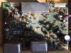
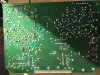
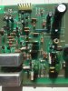
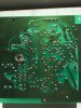
Some time ago I decided to recap my AR 1515 that I had built in late 70s. I relied heavily on the work of dlucy here: https://audiokarma.org/forums/index...upgrading-a-heathkit-ar-1515-receiver.891978/ (Thanks, dlucy!).
(Sorry,I did not found the trick to use a name instead of the long reference)
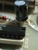
I changed the EC on all the boards, except the Control. On the Power Supply board, I changed too some diodes (regular and zener), as suggested. For the time being I kept the main caps, just changed the C3 6000 uF.
When reassambling I encountered, to my surprise, a couple problems.
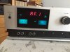
First the readout malfunctionned. All I was seeing was 1FFF (AM) or FF.F (FM): one of the legs of the capacitor that I had changed was not making contact with the front side trace of the board. After correction though, the problem was not gone; sometimes I could see 1550 (AM) or 89.1 (FM), or another numbers, or not numbers, and the movement of the tuning shaft had no effect. What intrigued me at the utmost, was the signal strength always stayed at the null position (FM, here we have no more AM stations).
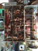
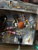
I began to investigate further and found that the oscillations on the RF board (FM and AM) were OK, I could see them changing on my scope as I turned the tuning shaft, but I could see the oscillations only when the IF board was disconnected; as soon as I connected the IF, I couldn see any oscillations. Strange!
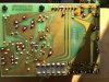
I rechecked my work, to see if any pieces that I had replaced was right (orientation) or for the presence of any bridge (solder): found none.
I then systematically reviewed the voltages on the boards, and found the following:
I measured the voltage (pins 1 and 2) on the power supply board (P802)
(The TABs do not seem to work here)
Pin 1 Pin 2 Comment
-16,6 17,1 P802 not connected
-13,7 13,7 P802 connected; PreAmpl and Control On (Always will be)
-10,2 9,8 RF connected (FM)
-9,5 9,0 RF connected (AM)
-12,6 12,4 IF connected (FM)
-13,5 13,5 IF connected (AM)
-7,1 6,4 Multiplex (FM)
-13,7 13,7 Multiplex (AM)
-13,6 13,6 Counter REadOut (FM or AM)
-10,3 9,9 Counter ReadOut + RF (FM)
-9,6 9,1 Counter ReadOut + RF (AM)
-4,7 3,7 Counter ReadOut + RF (FM) + IF (FM)
-8,5 8,0 Counter ReadOut + RF (FM) + IF (AM)
-4,1 3,1 Counter ReadOut + RF (FM) + IF (FM) + Multiplex (FM)
-8,5 8,0 Counter ReadOut + RF (FM) + IF (FM) + Multiplex (AM)
As we can see, there is a marked drop when the IF board is added. But the board seems OK!? Or have I something overlooked ?
After days searching, I need another head the point me on the right track.
Helios
(Sorry,I did not found the trick to use a name instead of the long reference)
I changed the EC on all the boards, except the Control. On the Power Supply board, I changed too some diodes (regular and zener), as suggested. For the time being I kept the main caps, just changed the C3 6000 uF.
When reassambling I encountered, to my surprise, a couple problems.
First the readout malfunctionned. All I was seeing was 1FFF (AM) or FF.F (FM): one of the legs of the capacitor that I had changed was not making contact with the front side trace of the board. After correction though, the problem was not gone; sometimes I could see 1550 (AM) or 89.1 (FM), or another numbers, or not numbers, and the movement of the tuning shaft had no effect. What intrigued me at the utmost, was the signal strength always stayed at the null position (FM, here we have no more AM stations).
I began to investigate further and found that the oscillations on the RF board (FM and AM) were OK, I could see them changing on my scope as I turned the tuning shaft, but I could see the oscillations only when the IF board was disconnected; as soon as I connected the IF, I couldn see any oscillations. Strange!
I rechecked my work, to see if any pieces that I had replaced was right (orientation) or for the presence of any bridge (solder): found none.
I then systematically reviewed the voltages on the boards, and found the following:
I measured the voltage (pins 1 and 2) on the power supply board (P802)
(The TABs do not seem to work here)
Pin 1 Pin 2 Comment
-16,6 17,1 P802 not connected
-13,7 13,7 P802 connected; PreAmpl and Control On (Always will be)
-10,2 9,8 RF connected (FM)
-9,5 9,0 RF connected (AM)
-12,6 12,4 IF connected (FM)
-13,5 13,5 IF connected (AM)
-7,1 6,4 Multiplex (FM)
-13,7 13,7 Multiplex (AM)
-13,6 13,6 Counter REadOut (FM or AM)
-10,3 9,9 Counter ReadOut + RF (FM)
-9,6 9,1 Counter ReadOut + RF (AM)
-4,7 3,7 Counter ReadOut + RF (FM) + IF (FM)
-8,5 8,0 Counter ReadOut + RF (FM) + IF (AM)
-4,1 3,1 Counter ReadOut + RF (FM) + IF (FM) + Multiplex (FM)
-8,5 8,0 Counter ReadOut + RF (FM) + IF (FM) + Multiplex (AM)
As we can see, there is a marked drop when the IF board is added. But the board seems OK!? Or have I something overlooked ?
After days searching, I need another head the point me on the right track.
Helios