• The move to the new server is done. There are some software and database maintenance updates in process. This has us passing the hat around to help out. We appreciate any donations. Seriously, even a dollar helps. The payment page may be found here - https://www.audiokarma.org/support.html

Heathkit IG-5218 sine-square wave audio signal generator issues

MKG

Elvish-mark’d abortive, rooting hog
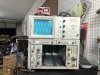
I bought a Heathkit IG-5218 sine-square wave audio signal generator on eBay.
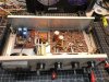
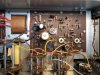
When I opened it up, a number of wires were clipped.

Found the assembly manual for an IG-18 and reconnected wires and fired it up.
After calibrating it it’s putting out a beautiful sine wave, but it’s having issues with a square wave.

I followed the troubleshooting chart and checked transistors q6, q7, and q8 and they all test good.
Used deoxit on control r101.
Checked capacitor c8 and it was over 450uf, replaced it with what I had on hand (a 220uf, 22uf, and 10uf capacitors wired in parallel).

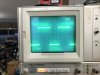
I still don’t think I’m getting a proper square wave. I almost have it, although the vertical is really faint (keep in mind that I’m still learning how to use my oscilloscope).

Any ideas on what to check next?
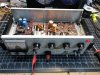
23978E23-9F8D-405D-B934-799CE731F049.jpeg 7D77D88A-17CC-4BCC-A42E-C144642279DE.jpeg 98EAD711-6B54-4EA7-A8A1-A70E90AC2186.jpeg A47347DC-676B-4BA1-A7F8-65CA19A69FE1.jpeg ECA95472-917F-4857-B358-74A37E980A90.jpeg
 
Register to hide this ad
I use a rebuilt IG-18 sometimes, and from your square wave photo I'd be inclined to agree, it's capable of better than that - I'd expect it to look as 'clean' as the sine does, with much better symmetry than in your photo (you should be able to adjust the symmetry with R16 - it's in the manual). I assume the 'fuzziness' around the square wave trace is due to the camera / photo ?

I'm not sure about the leading edge 'overshoot' (did you trim the scope probe ?). The rise time spec. for the square wave is 50nS, so the vertical trace could look 'faint' depending upon your scope bandwidth etc.
 
Tried adjusting symmetry, didn’t seem to do anything except lengthen or shorten the top or bottom line, it’s set in that photo to as even as I could get them.

Fuzziness is from my phone camera, bad angle.

Scope bandwidth is 200mhz. I’m using aftermarket probes, and thank you, I forgot to set it’s little trim screw (I’m new to this).

Any idea what else I should check while I’m fiddling with it tomorrow? Would any photos of anything potentially help track down the issue?

it could very well be user error with my scope.
 
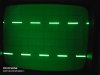
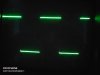
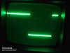
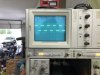
I just put an IG-5218 (in more or less original condition) on an old scope to give you an idea what I meant by 'clean' - I haven't found my notes yet, so I'm not sure what I had to fix on this one (I have an IG-18 as well), but not much if I remember correctly.

IMG_20200228_174554.jpg IMG_20200228_174034.jpg IMG_20200228_174200.jpg

I think the first couple of pics give you a better idea of the symmetry, they're about as 'equal' as I could get them 4-5 yrs ago, and there was no problem adjusting. The 3rd pic I tried to get a better look at the vertical part of the trace, but it's 'limited' by the 12Mhz bandwidth of the scope (I did say "old" scope). Any extra fuzziness in the pics is just the intensity set too high.

The Sq. wave section is around Q6, Q7 & Q8 - maybe take a look at the voltages in that section vs. the manual schematic ? It does show voltages across the adjustment range of R16 (e.g., R16 fully CCW & fully CW). Also, personally, I'd just use the 220uF cap for C8 for the time being (C8 was probably spec'ed at something like +50/-10% anyway). There may be other caps out of spec as well.

Feel free to pm me your email address if you need a pdf copy of the IG-5218 manual.
 
  • Like
Reactions: MKG
Thanks for your help.
I have the IG-18 manual and my understanding is that it is the same as the IG-5218 except for some cosmetic changes.

I compensated/trimmed my probes (first time, thank god for YouTube tutorials).

Then adjusted symmetry. Mine is looking much like yours now, so I do believe it’s good to go. I think I was expecting to see the vertical lines clearly, and I guess that’s not the case.

as you said, I do have a few more out of spec caps to replace, and then I’ll probably “green” it to get lower distortion.

Last question- the meter on mine only responds to the sine wave, not to the square wave- is that normal?

Thanks again!
DA265F81-3E5E-4ADA-8792-5C2355B375E8.jpeg
 
That looks a lot better - and with the 200Mhz scope, you should be able to see the vertical part of the sq. wave quite easily if you stretch out the time base.You can probably even measure the rise time.

The meter signal is taken from the sine wave generator output. It's not used for the sq. wave output. The sq. wave output is basically only 0V or a +Vdc value, with about 50% duty cycle. Note - both sets of output terminals are active at the same time, and can be adjusted independently for level.

The IG-18 I referred to before has also been modified - I used the kit from http://www.d8apro.com/NewKits.html It works well, and was very straightforward.
 
Back
Top Bottom