• The move to the new server is done. There are some software and database maintenance updates in process. This has us passing the hat around to help out. We appreciate any donations. Seriously, even a dollar helps. The payment page may be found here - https://www.audiokarma.org/support.html

Heathkit W-5M done! Bass Balance question

You'll need a pretty good transformer to run a Williamson design. The circuit uses a good deal of feedback, but with a decent OT, it is not a problem, but with a hammond, it might be....

I think the S-265-Q won't have any problems in this situation.

read about it here:
http://gregory.webng.com/W4/The_Williamson_Amplifier.pdf

hopefully my hosting bandwidth won't runneth over...please download it only once and save it

My recent experience with Hammond PP OPTs has been pretty decent although I admit that I haven't used one to replace a 309/458.

As you know, the original Williamson circuit wasn't without it's own stability issues. Thus Williamson's mods in the second article to add the "speedup" cap across the FB resistor and the addition of the phase comp network at output of the input voltage amp. Heath went beyond this by addition of their "tweeter-saver" network across the 16 ohm tap so even at this stage of the design's development, they were still concerned about the stability issue in spite of decent Peerless OPTs. Overall, with the additional stability considerations in the W5, lesser OPTs should be able to be successfully fitted...However...As I continue to consider the OP's current situation, I'm thinking that his best options will be either the original Heath part# as a replacement, an exact rewind or an electrically exact copy. Any other OPT will most likely require some adjustment of the feedback and phase comp components for optimum operation. This requires equipment and knowlege.

FWIW, based on the lit of the era, Williamson would not have considered the W5 as a true Williamson design because the output stage was UL. He apparently considered this circuit to be an unacceptable deviation from his original vision.
 
Dear god, you saved me. I almost screwed up big time.

In your opinion, if one was going to use a hammond output tx for a w5m amp. Which would it be?

If I were to use a Hammond for a W5 Clone I'd go for the 1650F but would be prepared to adjust the feedback and phase comp circuits to suit its specific characteristics.

If I had a choice and could afford it, I'd probably go for a custom design that more closely duplicates or improves upon the 16458 characteristics.

While working on the design of a PP #45 amp, I used the 309 as the OPT. With a very simple input amp and 6SN7 LTP driver (w/o CCS), I was able to achieve -1dB ~80KHz with no feedback. IOW, the HF performance of these OPTs is quite good.
 
Steve-O I check the resistance between V3-V4 #3 pins , nothing! however I have a second W-5M that is dead and the resistance between its pins is 500 Ohms... maybe i should try that one in my rebuild? there is a bit of black goo glazing its wires, but if it works at least I would know that the problem. Then again I wouldn't mind a non stock replacement, but choosing a 4.8.16 speaker tap is a turn off as my Mono JBL is 16 ohms but my Klipsch are 8 ohms. Seems like a healthy disscussion on the replacement OP tranny I will follow closley.
Again thanks,
Kirk
 
If I were to use a Hammond for a W5 Clone I'd go for the 1650F but would be prepared to adjust the feedback and phase comp circuits to suit its specific characteristics.

If I had a choice and could afford it, I'd probably go for a custom design that more closely duplicates or improves upon the 16458 characteristics.

While working on the design of a PP #45 amp, I used the 309 as the OPT. With a very simple input amp and 6SN7 LTP driver (w/o CCS), I was able to achieve -1dB ~80KHz with no feedback. IOW, the HF performance of these OPTs is quite good.

Once I realized the mistake I was making, again thanks, I looked up tx's and fond the 1650f as well.

I don't have a problem with adjusting the negative feedback from the OPT to the plate of the 12au7.

I'm going to finalize all my parts decisions tomorrow after I sleep and then order everything.

One reason I'm trying to stick with readily available parts is, if these work out, I have a few people who are going to want their own pairs.

I'll have to post some pics of the 40 watt class A amp me and my buddy made.
 
I'll have to post some pics of the 40 watt class A amp me and my buddy made.

It works because my friend designed it, it also works because I put it together.
Mostly. :D

Prototype development model. 40 watts continuous Class-A. Flat 14 Hz to 30 kHz. Mostly handwired by the intermittently shocked Whitey.

My buddy has it, and sense he is so busy with school, the new wife, the new baby.

I vote it comes back to me. :naughty:
 

Attachments

  • Tube amp resized#1.jpg
    Tube amp resized#1.jpg
    10.9 KB · Views: 28
  • tube amp resized#2.jpg
    tube amp resized#2.jpg
    11.2 KB · Views: 34
Steve-O I check the resistance between V3-V4 #3 pins , nothing! however I have a second W-5M that is dead and the resistance between its pins is 500 Ohms... maybe i should try that one in my rebuild? there is a bit of black goo glazing its wires, but if it works at least I would know that the problem. Then again I wouldn't mind a non stock replacement, but choosing a 4.8.16 speaker tap is a turn off as my Mono JBL is 16 ohms but my Klipsch are 8 ohms. Seems like a healthy disscussion on the replacement OP tranny I will follow closley.
Again thanks,
Kirk

Hi:

I'd do just that if I were in your position.

After sleeping on the situation, I think the best option for you if you want to get your W5 operating as designed is to replace your bad OPT with a good one from a junker W5 much as you propose. Fitting any other OPT will probably require you to make adjustments to component values and maybe even make minor circuit revisions. With the original OPT PN this work has already been done for you. Hopefully you'll be using the 16458 verson of the OPT.

Good luck
 
As you know, the original Williamson circuit wasn't without it's own stability issues.

Drawing from measurements, I can attest to that. There is a light LF instability in the two williamsons I've seen, the W4 and the C500a. I haven't seen a square waves from any, but I might try that sometime on one of my W4s to see any ringing, etc.

Thus Williamson's mods in the second article to add the "speedup" cap across the FB resistor and the addition of the phase comp network at output of the input voltage amp. Heath went beyond this by addition of their "tweeter-saver" network across the 16 ohm tap so even at this stage of the design's development, they were still concerned about the stability issue in spite of decent Peerless OPTs.

The tweeter save was also partially implemented to allow turn-on with no speaker connected, though i would not recommend this.

Overall, with the additional stability considerations in the W5, lesser OPTs should be able to be successfully fitted...However...As I continue to consider the OP's current situation, I'm thinking that his best options will be either the original Heath part# as a replacement, an exact rewind or an electrically exact copy. Any other OPT will most likely require some adjustment of the feedback and phase comp components for optimum operation. This requires equipment and knowlege.

Agreed, the best part of the W5 was the transformer, would be hard to call it a 'copy' without it, since there are many other Williamson designs. I also wouldn't use 12AU7s here, but rather octal tubes: 6SN7s, or the noval 6CG7s in a pinch.

FWIW, based on the lit of the era, Williamson would not have considered the W5 as a true Williamson design because the output stage was UL. He apparently considered this circuit to be an unacceptable deviation from his original vision.

I recall someone mentioned he was infuriated at the ultralinear concept in the design. I found that rather funny:D. It was implemented is most every 'williamson' then, save for a few designs. I have a pair of TO-300's i'll probly turn into one.

Aside, has anyone implemented the improvements in this article (http://stiftsbogtrykkeriet.dk/~mcs/Williamson/index.html) to any of the commercial Williamson amps? I was thinking about it :dunno:, need a little motivation.
 
Drawing from measurements, I can attest to that. There is a light LF instability in the two williamsons I've seen, the W4 and the C500a. I haven't seen a square waves from any, but I might try that sometime on one of my W4s to see any ringing, etc.

The stock W4 sq wave performance is very poor IME. With NI 8 ohm resistor load there is major overshoot and poorly damped ringing. Throw a 1uF cap across the resistor and it spontaneously breaks into ~30-40KHz oscillation w/o input. With the wrong speaker or cable, tweeters die. Stability required addition of Dyna-like cap from UL tap of one output tube back to input cathode among other measures.

The C500As I've got are quite well behaved in stock form WRT to sq wave performance. Decent 1Khz and 10KHz with pure R load and a little overshoot and well damped ringing with 1uF in parallel. My biggest issue with the 500s is that the stock bias point eats KT66s...and all for just 12-15W of pure, class A triode power.

Aside, has anyone implemented the improvements in this article (http://stiftsbogtrykkeriet.dk/~mcs/Williamson/index.html) to any of the commercial Williamson amps? I was thinking about it :dunno:, need a little motivation.

Interesting coincidence! One of the projects on the bench at the moment is a Heath W3AM ground-up restoration inc all new paint for everything. As you probably know, this amp uses the fairly decent Acro TO-300 as its OPT. Performance seems to be on a par with the equivalent Peerless piece.

I'm going to do the circuit as the revised version of the W3 to start. I'll make some measurements and listen for a while then implement the changes suggested in the article you linked and compare. Completion of the amp should about coincide with completion of the Altec Carmels I'm modifying so those will be my test speakers. On paper it appears to be a good match.
 
Interesting coincidence! One of the projects on the bench at the moment is a Heath W3AM ground-up restoration inc all new paint for everything. As you probably know, this amp uses the fairly decent Acro TO-300 as its OPT. Performance seems to be on a par with the equivalent Peerless piece.

I'm going to do the circuit as the revised version of the W3 to start. I'll make some measurements and listen for a while then implement the changes suggested in the article you linked and compare. Completion of the amp should about coincide with completion of the Altec Carmels I'm modifying so those will be my test speakers. On paper it appears to be a good match.

Great! :thmbsp: I'd love to hear what you think of the changes, and of the amp in general, as I'm going to be putting those TO-300s to use soon as well.
 
Steve-O thanks for all the help on my poor W-5M. I think i am going to try the "Junker " Op. How can I be certain it is OK? i don't want to risk destroying all the work i've done prior.Here are some readings I took:
V3-V4 #6 pin to#6 pin:469 ohms
I also took readings from the B+ Primary to:
V3#3:255ohms
V3#6:139 ohms
V4#3:253 ohms
V4#6:149 ohms

do you think I can proceed? thanks.
Kirk
 
The stock W4 sq wave performance is very poor IME. With NI 8 ohm resistor load there is major overshoot and poorly damped ringing. Throw a 1uF cap across the resistor and it spontaneously breaks into ~30-40KHz oscillation w/o input. With the wrong speaker or cable, tweeters die. Stability required addition of Dyna-like cap from UL tap of one output tube back to input cathode among other measures.

If one were to want to add this cap to a W4, would the 390 picofarad value that Dynaco used, be a good starting point, between the bottom UL tap and the input cathode?

Also- was just comparing the Dynaco and W4 schematics... to preserve polarity/phasing, wouldn't you need to tap from the TOP UL tap, not the bottom? The W4 has one more stage (the second 6SN7, which adds gain after the phase splitter) than the Dynacos, so the polarity of the circuit should be reversed...

Also, I was reading the article cited, referring to fixing the bias on the first 6SN7 stage (input gain stage)... one idea came to mind: Instead of using his 1K (or 910 ohm) resistor, why not TWO 470 ohm resistors IN SERIES, with the feedback fed in BETWEEN the two resistors? That would also provide a place for the Dynaco-style compensation cap (the 390 or so picofarad cap mentioned above) to connect, in nearly the exact manner it's used in the Dynaco Mk II and MK III...

If I do my math right, that would alleviate the need for changing the feedback resistor or cap right? You'd have the same voltage ratio at the feedback insertion point... so the feedback would be the same ratio as original...

If that were done, the only additional mod would be to change the 33K resistor feeding B+ to the input stage, to 47K or so, to get grid bias for the phase splitter back in whack, as far as I can tell. Might be a pretty elegant way to deal with the stability and the IM distortion thing, all at once...

I've attached a modified schematic of what I'm thinking about... could folks check it out, and see if there's anything wrong with this setup?
 

Attachments

  • heathw4sch-stability&im-mod.JPG
    heathw4sch-stability&im-mod.JPG
    74.7 KB · Views: 45
If one were to want to add this cap to a W4, would the 390 picofarad value that Dynaco used, be a good starting point, between the bottom UL tap and the input cathode?

Also- was just comparing the Dynaco and W4 schematics... to preserve polarity/phasing, wouldn't you need to tap from the TOP UL tap, not the bottom? The W4 has one more stage (the second 6SN7, which adds gain after the phase splitter) than the Dynacos, so the polarity of the circuit should be reversed...

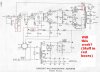
You're correct about the phasing. See below for what I did to my W4 to improve stability. The primary goal was improved 1KHz and 10KHz sq wave with 8 ohm resistive load and unconditional stability with any amount of capacitance across the load. These changes also limit bandwidth of the amp such that it's flat to ~20KHz, -1dB ~25KHz, and -3 dB~35KHz (2.83V across 8 ohms). This is in sharp contrast to the original Heath "spec" where they imply response out to beyond 100KHz. There are all kinds of squiggles beyond 30KHz in the response plot Heath provides suggesting problems beyond this freq. IMO the stock Chicago OPT simply isn't up to the task. The W5 easily outperforms the W4 WRT extended response and stability, no doubt due to the decent Peerless OPT employed. The W5 also sounds better than the W4 with and esp w/o mods.

If I were to do this exercise again, I would probably put a little more emphasis on extended response and a little less on sq wave appearance although with the glitches in the stock response beginning @ 30KHz, there may not be much room for improvement. It should be noted that the W4 design incorporates the "speed-up" cap across FB resistor, the phase comp network at the input to PI and the "tweeter saver" circuit on the output as stock circuit. Not much room for improvement w/o changing output iron. [edit] It's significant to note that the Heath instruction manual states "Under no conditions should shielded speaker lines be used and every attempt should be made to keep the capacity across the speaker lines to a minimum." The Stock W4 had stability issues from the get-go and Heath knew it.

Regarding the other changes you propose, they seem reasonable enough but I admit to not having giving them much thought. As I noted in an earlier post, I'll be implementing the stock and improved circuits in a W3 rebuild, do some measuring and listening and go from there. I'll certainly consider what you've proposed. Since the TO-300 OPT is much better than the one on the W4, I don't expect to be needing that cap from the OPT primary to input cathode.


W4MODS.jpg
 
Steve-O thanks for all the help on my poor W-5M. I think i am going to try the "Junker " Op. How can I be certain it is OK? i don't want to risk destroying all the work i've done prior.Here are some readings I took:
V3-V4 #6 pin to#6 pin:469 ohms
I also took readings from the B+ Primary to:
V3#3:255ohms
V3#6:139 ohms
V4#3:253 ohms
V4#6:149 ohms

do you think I can proceed? thanks.
Kirk


The resistances you measure are pretty much in the ballpark. Although there are indeeed some tests you can perform on the OPT out-of-circuit that can verify proper operation, they can get a bit involved and aren't 100%. Th real test is in the amp anyways. I'd proceed if I were you.
 
You're correct about the phasing. See below for what I did to my W4 to improve stability. The primary goal was improved 1KHz and 10KHz sq wave with 8 ohm resistive load and unconditional stability with any amount of capacitance across the load. These changes also limit bandwidth of the amp such that it's flat to ~20KHz, -1dB ~25KHz, and -3 dB~35KHz (2.83V across 8 ohms). This is in sharp contrast to the original Heath "spec" where they imply response out to beyond 100KHz. There are all kinds of squiggles beyond 30KHz in the response plot Heath provides suggesting problems beyond this freq. IMO the stock Chicago OPT simply isn't up to the task. The W5 easily outperforms the W4 WRT extended response and stability, no doubt due to the decent Peerless OPT employed. The W5 also sounds better than the W4 with and esp w/o mods.

If I were to do this exercise again, I would probably put a little more emphasis on extended response and a little less on sq wave appearance although with the glitches in the stock response beginning @ 30KHz, there may not be much room for improvement. It should be noted that the W4 design incorporates the "speed-up" cap across FB resistor, the phase comp network at the input to PI and the "tweeter saver" circuit on the output as stock circuit. Not much room for improvement w/o changing output iron.

Regarding the other changes you propose, they seem reasonable enough but I admit to not having giving them much thought. As I noted in an earlier post, I'll be implementing the stock and improved circuits in a W3 rebuild, do some measuring and listening and go from there. I'll certainly consider what you've proposed. Since the TO-300 OPT is much better than the one on the W4, I don't expect to be needing that cap from the OPT primary to input cathode.


W4MODS.jpg

Hi Steve,

Did you notice much of an audible change in the way the amp sounds from these changes? better? worse? Also, did you try a series R with the plate feedback capacitor to mitigate the bandwidth reduction? (Give it a step instead of a pure -20dB/decade cutoff)
 
Hi Steve,

Did you notice much of an audible change in the way the amp sounds from these changes? better? worse? Also, did you try a series R with the plate feedback capacitor to mitigate the bandwidth reduction? (Give it a step instead of a pure -20dB/decade cutoff)

The primary audible change I noticed was the elimination of an "edge" to the sound of vocal sibilants and on instruments like cymbal and triangle. My main concern however was the stability issue. I didn't want to be worrying about frying tweeters. Interestingly, I obtained my 1st W4 as part of a package deal that included a large home built speaker loaded with University drivers. Curiously, the T206 tweeter had an open voicecoil. I wonder why?

Regarding the addition of a resistor to the plate feedback cap, I did try that when I was developing the mods. Best sq wave performance was achieved with no resistance much like the Dyna circuit. However, there are other priorities than sq waves so if anyone wants to improve upon what I've done, by addition of that resistor, why not? I didn't keep notes on what I tried there so a first guess would be somewhere in the range of 47K-100K ohms and then go from there experimentally. OTOH, considering that the stock circuit is beginning to misbehave ~30KHz, I have to wonder if much improvement is possible.
 
Steve- if I wanted to experiment with starting the bandwidth limitation a bit later, would a cap smaller than 56pf do it? I'm thinking maybe like 33pf or so? Would that have any useful value, or would it need to be closer to 40-something to do anything useful?

Also, if I get the gist, the cap from anode to feedback is the dominant cap in this scheme... is it necessary to change the others (the one in the OPT secondary feedback and the one on the plate of the input tube) for this to work right? Or, are they just "optimizing" the factory values, or something like that?

Thanks!

Regards,
Gordon.
 
Steve- if I wanted to experiment with starting the bandwidth limitation a bit later, would a cap smaller than 56pf do it? I'm thinking maybe like 33pf or so? Would that have any useful value, or would it need to be closer to 40-something to do anything useful?

Also, if I get the gist, the cap from anode to feedback is the dominant cap in this scheme... is it necessary to change the others (the one in the OPT secondary feedback and the one on the plate of the input tube) for this to work right? Or, are they just "optimizing" the factory values, or something like that?

Thanks!

Regards,
Gordon.

There's absolutely nothing I did to my W4 that should be considered sacred inc the objective of unconditional stability and nice looking sq waves. If you're looking for a more extended response, by all means reduce the value of the plate feedback cap. I experimented with values as low as 12pF and all of them had some effect on response and sq wave appearance so the values you mention are reasonable. Also consider adding the step resistor as suggested by bricktop. FWIW, I found the first resonance of the OPT to be ~ 60KHz. It's probably a good idea to get amp response well down before this point.

You're correct, the plate feedback cap is dominant at ultrasonic frequencies. I would have preferred to have used only this cap and eliminate the cap across the feedback resistor but found that the two complemented each other in achieving my objectives The changes I made to this and the phase comp network are really minor tweaks of the stock values so these could be left alone w/o issue. Notice that the phase comp resistor is double the original value.
 
Perhaps we should start a new thread?..or these posts about the W4 moved to a new thread? Any moderators watching this?

Also, Gordon, be sure your plate feedback cap is rated for at least 1000V for a little margin, 500V caps won't do. Silver micas are the best (and also the most expensive), but ceramics will do as well.
good luck,:thmbsp: let us know how it turns out.
 
Back
Top Bottom