• The move to the new server is done. There are some software and database maintenance updates in process. This has us passing the hat around to help out. We appreciate any donations. Seriously, even a dollar helps. The payment page may be found here - https://www.audiokarma.org/support.html

Heathkit W5m delay timer

Thunderbud

Boyhowdy
Good morning, guys;

Am switching from tube to solid-state rectification, and am installing a delay timer to avoid making bottle rockets

out of my beloved Gold Lion KT66's. Bought a pair of 555-based boards with approx. 30 seconds of delay off the 'Bay, but a trusted friend says I want a good 60 seconds or more of delay. Any suggestions ? And no, I'm

not competent to swap values on the

board to change the RC time constant. Any suggestions ?


Thanks !
 
Register to hide this ad
That type of delay timer is available with adjustable delay times and that makes it easy. Of course that means spending more money for new devices.

If they are 555 based timers it is just a matter of changing a single resistor in each or replacing the resistor with a potentiometer to make it adjustable. Do you know anyone with decent soldering skills. Maybe your timer uses surface mount components, that would make it more difficult.

Then again a lot of people do not have any type automatic turn on delay.
 
That type of delay timer is available with adjustable delay times and that makes it easy. Of course that means spending more money for new devices.

If they are 555 based timers it is just a matter of changing a single resistor in each or replacing the resistor with a potentiometer to make it adjustable. Do you know anyone with decent soldering skills. Maybe your timer uses surface mount components, that would make it more difficult.

Then again a lot of people do not have any type automatic turn on delay.
Thanks for the reply, I Like Music; I can make any necessary parts-swaps on the boards, just don't know what the resistor value should be. A pot is a good idea, if I knew what resistor gets replaced with the pot. More research needed, I guess..
 
Oh, by the way-I don't mind replacing these with new components if using lengthening the delay on these will be a lot of trouble.That should have read " if using these will be a lot of trouble. "
 
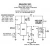
Below is a generic schematic of a 555 based delay on turn on timer.

The timing resistor and capacitor will usually be connected to pin 6 of the 555. The component values will be different for your timer.

The time delay is set by the ratio (RC time constant) of the resistance and capacitance connected to pin 6.

For example...

Doubling the value of the resistor or capacitor connected to pin 6 of the 555 would double the turn on delay. Usually a capacitor value is chosen and the value of the resistance is varied. The resistor may be replaced with a potentiometer for variable timing.

BTW your timer may have only 1 resistor connected to pin 6 of the 555. The fixed value resistor (RX-a) in my example sets the minimum delay.

555 DELAY TURN ON TIMER.JPG
 
…Am switching from tube to solid-state rectification, and am installing a delay timer to avoid making bottle rockets.
This statement raises a question. How are you going to alter the original circuit to effect turn on delay?

…Bought a pair of 555-based boards with approx. 30 seconds of delay off the 'Bay, but a trusted friend says I want a good 60 seconds or more of delay. Any suggestions?
Yes, question your friends assumptions. The difference between using solid state diodes VS the 5R4 rectifier is only a three second delay. Why would you need a 30 second delay let alone 60 seconds?

One additional question? Why would you want to install solid state rectifiers in place of the 5R4 rectifier tube? Doing so would alter the amplifier performance and require other, more complex, circuit changes to maintain safe operation.
 
Last edited:
Below is a generic schematic of a 555 based delay on turn on timer.

The timing resistor and capacitor will usually be connected to pin 6 of the 555. The component values will be different for your timer.

The time delay is set by the ratio (RC time constant) of the resistance and capacitance connected to pin 6.

For example...

Doubling the value of the resistor or capacitor connected to pin 6 of the 555 would double the turn on delay. Usually a capacitor value is chosen and the value of the resistance is varied. The resistor may be replaced with a potentiometer for variable timing.

BTW your timer may have only 1 resistor connected to pin 6 of the 555. The fixed value resistor (RX-a) in my example sets the minimum delay.

View attachment 781799
Well that certainly clarifies things. So in your generic circuit RX-a plus RX-b ( the pot at whatever setting it happens to be ) sets the delay. Thanks. As you say, my board may have only RX-a in place.
 
Please enlighten me: what function will be delayed with the amp?
Is it delay of B+ after power on ? ( not needed )
Is it protection of burn-out where mains disappears and comes back within a second or two ? That is
an uncommon but potentially damaging event, tubeamps are sensitive for this.
How and for how long the delay should be is next question.
 
This statement raises a question. How are you going to alter the original circuit to effect turn on delay?

Yes, question your friends assumptions. The difference between using solid state diodes VS the 5R4 rectifier is only a three second delay. Why would you need a 30 second delay let alone 60 seconds?

One additional question? Why would you want to install solid state rectifiers in place of the 5R4 rectifier tube? Doing so would alter the amplifier performance and require other, more complex, circuit changes to maintain safe operation.
Please enlighten me: what function will be delayed with the amp?
Is it delay of B+ after power on ? ( not needed )
Is it protection of burn-out where mains disappears and comes back within a second or two ? That is
an uncommon but potentially damaging event, tubeamps are sensitive for this.
How and for how long the delay should be is next question.
Yes, the purpose is to delay the application of voltage to the plates of the power tubes until after warm-up.
 
This statement raises a question. How are you going to alter the original circuit to effect turn on delay?

Yes, question your friends assumptions. The difference between using solid state diodes VS the 5R4 rectifier is only a three second delay. Why would you need a 30 second delay let alone 60 seconds?

One additional question? Why would you want to install solid state rectifiers in place of the 5R4 rectifier tube? Doing so would alter the amplifier performance and require other, more complex, circuit changes to maintain safe operation.
Altering the amp's performance is the idea - looking to " firm-up " the bass response.
 
Yes, the purpose is to delay the application of voltage to the plates of the power tubes until after warm-up.
If that is the purpose, a 30 second delay should be sufficient. Are you intending to use a relay, driven by the delay timer, to do the switching? Have you found a relay with the appropriate voltage and current rating?

Altering the amp's performance is the idea - looking to "firm-up " the bass response.
If I understand your intent, you are expecting the installation of solid state diodes to “firm-up” the bass response?

What will happen, if solid state diodes are installed, is that the B+ voltage will increase, because of the lower diode impedance compared to the 5R4 tube rectifier, unless you make additional modifications to the power supply section. If you do not reduce the extra B+, there will be additional power dissipation in the KT-66 tubes, which will shorten their life.
 
Last edited:
If that is the purpose, a 30 second delay should be sufficient. Are you intending to use a relay, driven by the delay timer, to do the switching? Have you found a relay with the appropriate voltage and current rating?

If I understand your intent, you are expecting the installation of solid state diodes to “firm-up” the bass response? Good luck with that.

What will happen is that the B+ voltage will increase, unless you make additional modifications to the power supply section. If you do not reduce the extra B+, there will be additional power dissipation in the KT-66 tubes, which will shorten their life.
 
Thanks for the response and the advice, but comments like " If I understand your intent, you are looking to " firm-up " the bass response ? Good luck with that. " are the reason I don't spend much time here. I asked for some advice, because I know there are some nice, helpful folks here ( some of which are clearly genius in the audio and electronics fields ). But your comments were arrogant, and condescending. Thanks but I don't need that kind of help. Thanks especially to I Like Music and the others who helped.

Bob.
 
Thanks for the response and the advice, but comments like " If I understand your intent, you are looking to " firm-up " the bass response ? Good luck with that. " are the reason I don't spend much time here. I asked for some advice, because I know there are some nice, helpful folks here ( some of which are clearly genius in the audio and electronics fields ). But your comments were arrogant, and condescending. Thanks but I don't need that kind of help. Thanks especially to I Like Music and the others who helped.

Bob.
Bob,

I apologize for the unnecessary comment. Since it did not add anything to the discussion, I have removed it. I sincerely hope that your project goes well.
 
Last edited:
Not condescending or arrogant at all ... just pointing out options, and potential benefits and compromises going with a timer delay.

And yes, 30 seconds should be MORE than adequate. Main thing is to tame the inrush when you first power on, and usually 2-3 seconds is more than enough to get the heater circuits up to where they can more gracefully handle the full load.

Also worth repeating (at risk of sounding condescending or arrogant?) ... the BIG issue for me is power blips on tube equipment. Those quickie blinks from storms or system trips can kill amps especially. A very good idea to add a NON-LATCHING power adapter that will cut power and require a manual reset. These are mostly aimed at contractors who really really don't want a power tool to take off on them if power is interrupted. Best $20 protection investment you may ever make.

TRC 90033 Shockshield White Portable GFCI Plug with Surge Protection
 
I do not know which device the OP has, but a number of them work that way or can be easily modified. You have to push to start so to speak.

I recommend this for the ones that I build for friends.

A manual reset after a power fault can be used to protect the entire system in addition to a delay on turn on timer.
 
Bob, were you intending to delay the application of AC voltage to the B+ rectifier, or DC B+ to the amp circuits (if so, then which particular circuit link as there is a CLC filter) ? There is a related difference with respect to surge currents in different parts of the circuit (and hence fuse selection and performance), and transient lack of cathode bias on the output stage, and probably initial output signal transient to speakers.
Ciao, Tim
 
What will happen is that the B+ voltage will increase, unless you make additional modifications to the power supply section. If you do not reduce the extra B+, there will be additional power dissipation in the KT-66 tubes, which will shorten their life.

A bigger issue than a need to delay the B+ is the much , much higher voltage you will have by using a SS rectifier. The 5R4 stock rectifier tube drops over 60vdc in this amp. which results in a B+ of 450v. If you put in SS rectifier your B+ will be around 500v.! This will be rather stressful for the caps and other components in your circuit. You will also need to address your excess voltage with a dropping resistor or another choke.
 
I suggest using more than 30 seconds for warmup, although that it is an excellent starting point. Here's why. (I'm excerpting and condensing this from a monograph I'm preparing on the subject.)

Thermal stress in a filament at startup is enormous. What really matter is the delta T per second. A standard Sr or Ba cathode coating must be heated to approximately 1,100 ºC. Taking 30 second is 1100 ºC / 30 Sec = 37 ºC / Sec. Going up to 120 seconds drops that to 9 ºC / Sec. This is a considerable difference. And it matters.

Tomer wrote extensively about the problems of thermal stress:
“Whenever a heater is turned on from a cold start, there is a very high initial surge of current. This is because the cold resistance of the heater is many times less than its hot resistance. The surge current has a tendency to cause the heater to convulse and stretch, and it is this effect which leads to many premature heater failures.”—Robert B. Tomer, Getting the Most Out of Vacuum Tubes by Robert B. Tomer, Howard W. Sams & Co., Inc. (1960) Pages 11-12

“Various means have been used to reduce this high initial surge current. Many recent TV sets have incorporated a surge-limiting resistor having a negative temperature coefficient. These resistors offer their maximum resistance when cold, and gradually decrease in resistance as they become hotter. In this way, they counteract the opposite characteristics of the heater. The use of these resistors is strongly recommended by all tube manufacturers. As much as a four-to-one decrease in heater burnout rate can be expected when surge-limiting resistors are used.”—Robert B. Tomer, ibid, Pages 12-14​

For further reading see Tomer as well as:
“Kindness to Filaments: A Study of Different Filament Supply Regimes” by John A. Harper (2004 April 15)
www.john-a-harper.com/FilamentHeating
 
A bigger issue than a need to delay the B+ is the much , much higher voltage you will have by using a SS rectifier. The 5R4 stock rectifier tube drops over 60vdc in this amp. which results in a B+ of 450v. If you put in SS rectifier your B+ will be around 500v.! This will be rather stressful for the caps and other components in your circuit. You will also need to address your excess voltage with a dropping resistor or another choke.

Excellent advice. The rectifier drop is critical. Many circuits derive bias or coupling voltages (cathode, grid, screen, etc.) using dropping resistors from B+. So a higher B+ alters those points. In the case of bias it shifts the bias point which is bad as it stresses the tube and results in failure.

A MOSFET regulator can be used as a variable resistor to precisely regulate B+, and add a turn-on delay to prevent damage to the cathodes from pulling a current before the filament is hot. This requires a heatsink, of course.
 
Back
Top Bottom