I am working my way through diagnosing a Marantz / Philips CD60 that will not read discs. The service manual is pretty good but I am having some trouble using my oscilloscope - which I've never used before. It's a Tektronix 2236 from an EE friend that he hadn't used since college. He says it works but I have no idea how to test it, so I'm just assuming it does work.
Before focusing on my specific issue, here's the background:
-Reported working before the previous owner attempted a re-cap.
-Now has all new electrolytics.
-Various solder pads were destroyed during the re-cap, I have fixed them all as far as I can tell.
-I also re-flowed various cold solder joints.
Current condition:
-Powers on.
-Tray ejects / retracts fine.
-When a CD is inserted, it will not read the CD.
-The CD spins briefly, and then stops.
-The display reads "00 00:00"
The service manual (available on HFE) requires the use of a multimeter, an oscilloscope, and various test CDs. I have a multimeter and know how to use it, I have an oscilloscope and have never used it before, and I don't have any official test CDs.
The service manual provides a troubleshooting fault finding tree, the first brand of which ("A"), I will copy below.
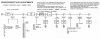
Following this tree ... I pass A-1 since my display works, I pass A-2 since there are no clicks or pops (as far as I can tell), I pass A-3 since I can load a disc in the tray, but I cannot pass A-4 since the TOC never displays.
So, I move to branch "B":

I engage B-1 service mode by powering it on with "STOP/CM" and "PLAY" both depressed. I can move through four settings (0, 1, 2, and 3). From here, the manual is light on details. It seems like I should then look at the "B-2 B0, B1, B2, B3 SIGNALS" section:
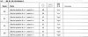
This chart makes little to no sense to me. The "low" and "high" are in a column with the oscilloscope icon, and "32", "33", "34", and "36" are in the column with the test point icon.
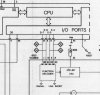
I found these test points in the schematic diagram, in the "SERVO" section between the 6530A/2 and the TDA8809 "RADIAL ERROR PROCESSOR".
Great. But .. uh.
What do I measure?
How do I measure it?
What settings on the oscilloscope do I use?
Where do I connect the oscilloscope leads?
Not knowing this, I took the clues from the "B" branch of the fault finding tree (boxed in red).
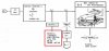
In settings "0" and "1", pushing Search >> or Search << results in the laser eye moving from side to side. I figure this is good, confirming that the "ARM FRICTION" and "FLEX FOIL" are OK. In setting "2", the "turntable" motor starts spinning very fast. In setting "3", I'm not sure what happens. In any case, no errors are thrown. I assume this is good?
Moving along. I do still have a working display, although it still displays "00 00:00". I move past B-1 and into B-3: CHECK OF THE PHOTODIODES.
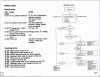
According to B-3, I am supposed to hook the multimeter up to four test points which appear to correspond to the two LEDs and two sensors in the laser pickup assembly.

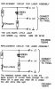
Drawing 38314A12 gives an idea, apparently, of what the oscilloscope is supposed to show after the unit is powered on.

Now, here's where I run into some practical questions. These test points ("4", "6", "7", and "8"), are present as pins on the ribbon connector socket for the CDM4 assembly. HOW AM I SUPPOSED TO HOOK MY MULTIMETER LEADS TO THEM?
Here's a picture of the underside of the harness connector, and my scope lead. There's obviously nothing to hook it to.
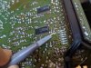
So, I tried to just CAREFULLY touch the exposed hook to each pin (pins 3,4, 5, 6 correspond to the test points), while holding the scope lead ground to a grounded pin (pin 7). When I did this, however, my scope did nothing. The line remained perfectly flat, at 0V.

Am I making this connection correctly? Am I missing some obvious place that I can hook my leads to?
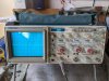
Here is the scope display - and you can see all my settings as well. Please let me know if you spot anything wrong here.
If the settings ARE correct, and if my simple method of touching the leads to the test points is correct, I suppose this means my photodiodes are bad!
THANK YOU in advance for any help or advice or pointers here!
Before focusing on my specific issue, here's the background:
-Reported working before the previous owner attempted a re-cap.
-Now has all new electrolytics.
-Various solder pads were destroyed during the re-cap, I have fixed them all as far as I can tell.
-I also re-flowed various cold solder joints.
Current condition:
-Powers on.
-Tray ejects / retracts fine.
-When a CD is inserted, it will not read the CD.
-The CD spins briefly, and then stops.
-The display reads "00 00:00"
The service manual (available on HFE) requires the use of a multimeter, an oscilloscope, and various test CDs. I have a multimeter and know how to use it, I have an oscilloscope and have never used it before, and I don't have any official test CDs.
The service manual provides a troubleshooting fault finding tree, the first brand of which ("A"), I will copy below.
Following this tree ... I pass A-1 since my display works, I pass A-2 since there are no clicks or pops (as far as I can tell), I pass A-3 since I can load a disc in the tray, but I cannot pass A-4 since the TOC never displays.
So, I move to branch "B":
I engage B-1 service mode by powering it on with "STOP/CM" and "PLAY" both depressed. I can move through four settings (0, 1, 2, and 3). From here, the manual is light on details. It seems like I should then look at the "B-2 B0, B1, B2, B3 SIGNALS" section:
This chart makes little to no sense to me. The "low" and "high" are in a column with the oscilloscope icon, and "32", "33", "34", and "36" are in the column with the test point icon.
I found these test points in the schematic diagram, in the "SERVO" section between the 6530A/2 and the TDA8809 "RADIAL ERROR PROCESSOR".
Great. But .. uh.
What do I measure?
How do I measure it?
What settings on the oscilloscope do I use?
Where do I connect the oscilloscope leads?
Not knowing this, I took the clues from the "B" branch of the fault finding tree (boxed in red).
In settings "0" and "1", pushing Search >> or Search << results in the laser eye moving from side to side. I figure this is good, confirming that the "ARM FRICTION" and "FLEX FOIL" are OK. In setting "2", the "turntable" motor starts spinning very fast. In setting "3", I'm not sure what happens. In any case, no errors are thrown. I assume this is good?
Moving along. I do still have a working display, although it still displays "00 00:00". I move past B-1 and into B-3: CHECK OF THE PHOTODIODES.
According to B-3, I am supposed to hook the multimeter up to four test points which appear to correspond to the two LEDs and two sensors in the laser pickup assembly.
Drawing 38314A12 gives an idea, apparently, of what the oscilloscope is supposed to show after the unit is powered on.
Now, here's where I run into some practical questions. These test points ("4", "6", "7", and "8"), are present as pins on the ribbon connector socket for the CDM4 assembly. HOW AM I SUPPOSED TO HOOK MY MULTIMETER LEADS TO THEM?
Here's a picture of the underside of the harness connector, and my scope lead. There's obviously nothing to hook it to.
So, I tried to just CAREFULLY touch the exposed hook to each pin (pins 3,4, 5, 6 correspond to the test points), while holding the scope lead ground to a grounded pin (pin 7). When I did this, however, my scope did nothing. The line remained perfectly flat, at 0V.
Am I making this connection correctly? Am I missing some obvious place that I can hook my leads to?
Here is the scope display - and you can see all my settings as well. Please let me know if you spot anything wrong here.
If the settings ARE correct, and if my simple method of touching the leads to the test points is correct, I suppose this means my photodiodes are bad!
THANK YOU in advance for any help or advice or pointers here!