• The move to the new server is done. There are some software and database maintenance updates in process. This has us passing the hat around to help out. We appreciate any donations. Seriously, even a dollar helps. The payment page may be found here - https://www.audiokarma.org/support.html

Help Identifying SGS Transistor

Jake Joseph

New Member
Hi folks - working on a Kirksaeter RTX 400. I've been unable to find a schematic - I can find a schematic for a RTX 400, but not *this* RT X 400 (the power supply circuit is extremely different from any of the published schematics - extremely different).

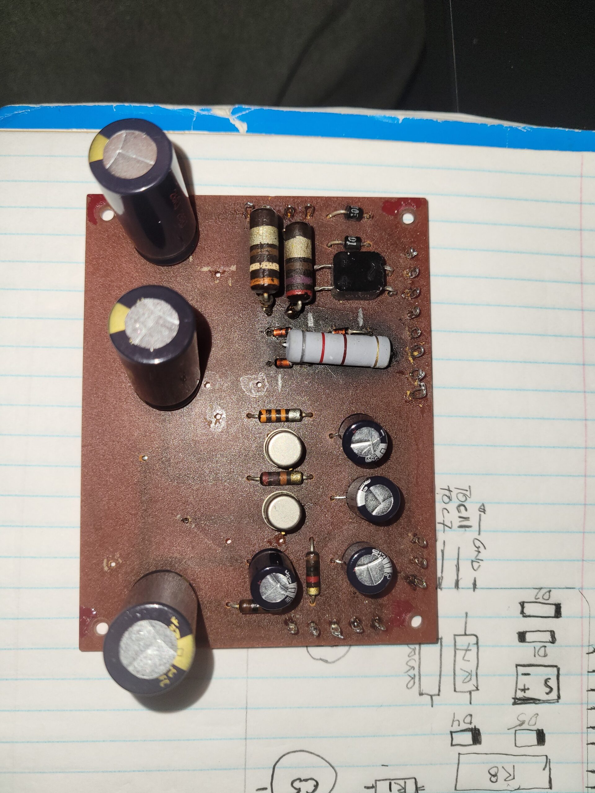
The power board had a blown zener, I've replaced that, and now the "regulator" circuit for the negative rail is non operational - there's a transistor and a resistor, and the transistor has a dead short between two of its leads. So that's not good, and is likely the reason for the negative rail being non functional.

The problem is since I don't have a schematic, I gotta go by what's on the transistor can.

The NPN for the positive rail is labeled SGS C426 534 - its a TO-5 can
The likely PNP for the negative rail is labeled SGS DW6697 909 - its a TO-5 can

I've found C426 specs and data sheet. I can even buy spares. I cannot find any reference anywhere to the DW6697. In some of the schematics, the NPN doing the same function is listed as a BC109. That's close to the specs of the C426, and it's compliment PNP is a BC179. The problem is I can probably figure out the pinout of the NPN, but I'd be guessing at the pinout of the PNP.

I've looked at old SGS cross reference guides, and haven't been able to find any reference to C426.

Any advice appreciated.
 
Register to hide this ad
I can't be of any help to you about the transistors, but it's funny that a resistor would fail to a dead short condition. Could that resistor be a zero-ohms jumper? Those usually have just a black color band on them.
 
all power supply transistors are bc109 .according to my schematic that is 2 supplies positive only and amp cap coupled output .
 
I can't be of any help to you about the transistors, but it's funny that a resistor would fail to a dead short condition. Could that resistor be a zero-ohms jumper? Those usually have just a black color band on them.
Ah, I don't think that the resistor is a dead short, I think that the transistor is a dead short - sorry if that wasn't clear.
 
post some pictures please .
and welcome to AK
20230303_173443-scaled.jpg
 
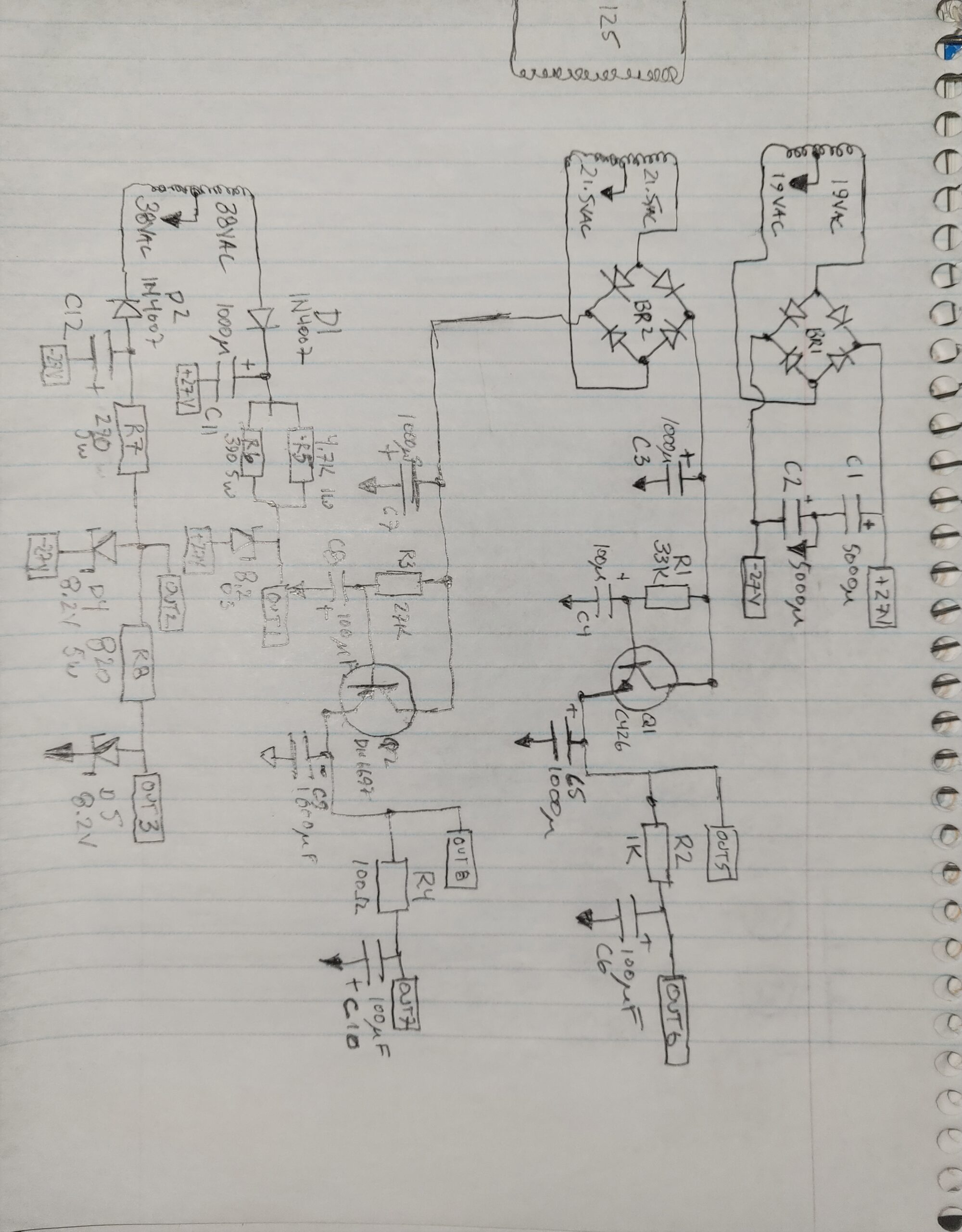
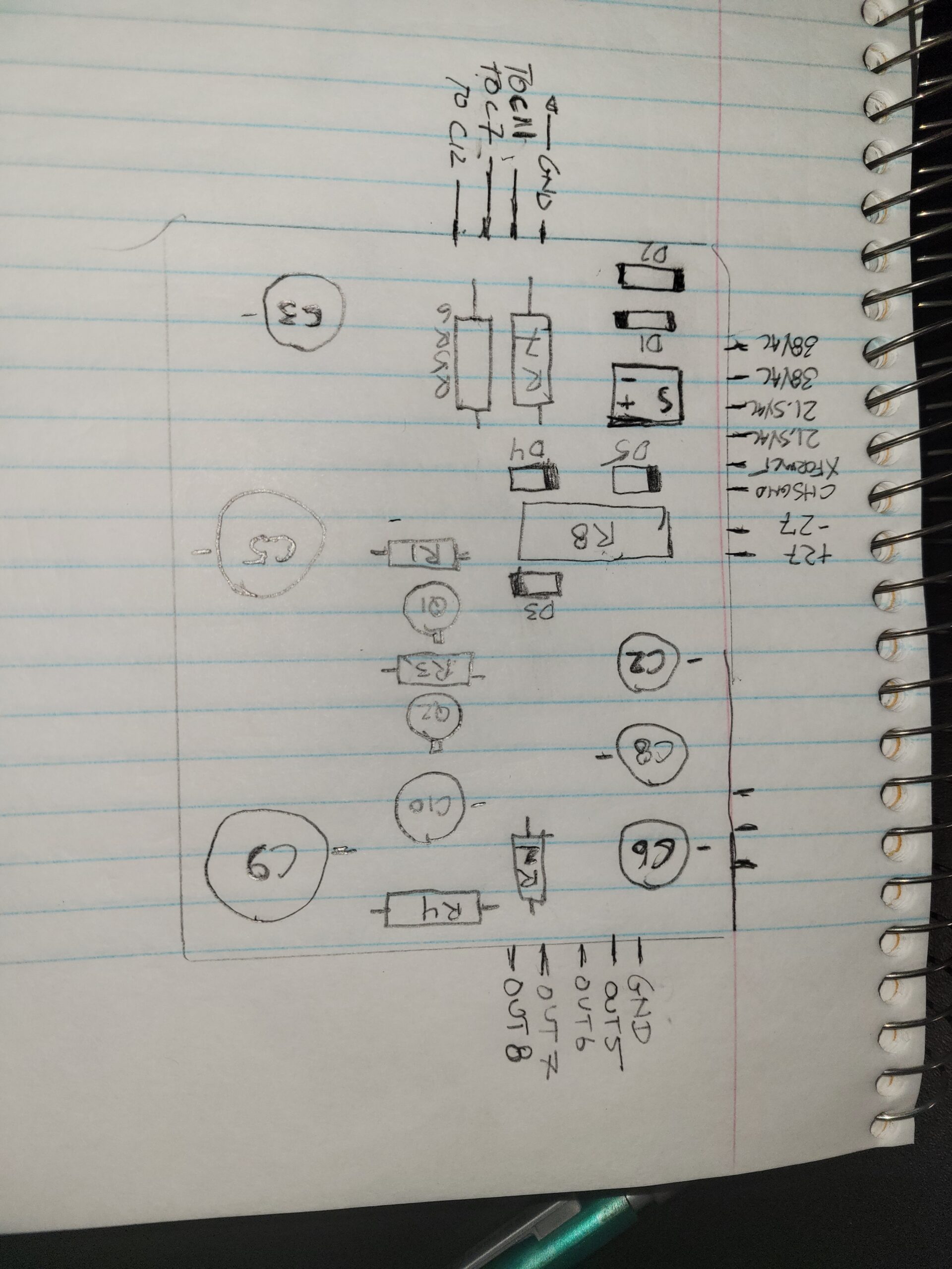
Unfortunately, neither one of those is close to what I got. The power transformer has 3 secondaries - a 76VAC CT, a 43VAC CT, and a ~40VAC CT, the 76VAC is half-wave rectified and the 43 and 40 VAC have bridge rectifiers. The filtering occurs between the 37V and 27V rails, rather than 37V to ground, likely to be able to use 35V electrolytics.

In addition, there's three zeners in the power supply, 8.2V
 
Welcome to AK.

For the shorted transistor, maybe from the not-shorted junction you can find out whether Germanium or Silicon. Usually, pinout of TO5 is same for all transistors.

Myself, I recently bought a RTX700. It has a class-B power stage, it is supposed to be not working, so probably I will face alike problems.....Even my main amp heatsinks are oriented differently from internet pictures.....
the class B stages using Germanium PNP and Silicon NPN big power transistors having base and emitters wired together will be a challenge.....

Indeed all the schematics I copied indicate a BC109 in the power rail. As the Elektrotanya one appears a NVHR marked copy, I checked the NVHR site and apart from this one no other Kirksaeter schematics to be found....
However, as a BC109 is not TO-5, you have something different. Myself, I would just guess and take any not-low-HFE transistor, maybe consider 2N2219A and 2N2905 or alike for TO-5 can transistors.

BTW your picture indicates new capacitors. If it was not done by you, try to check whether the circuit is original or if it was reworked.

There also seems no need for a negative supply, although the small amp stage using an AC172 in the schematic suggests different, but I think they just did draw the AC172 wrong way around.
 
Last edited:
Interesting, I wonder whether they used different tuners or preamp schematics during this Germanium to Silocon transition era.....

This makes me realize, none of the schematics I found, contain any information about the tuner front end, apart from the "ZF" amp. Did you find anything?
 
Interesting, I wonder whether they used different tuners or preamp schematics during this Germanium to Silocon transition era.....

This makes me realize, none of the schematics I found, contain any information about the tuner front end, apart from the "ZF" amp. Did you find anything?


I found this schematic, which has the tuner front ends, and says that it's applicable to RT X 400 - I cannot remember where I found this one.

https://ahcanalysis.com/wp-content/uploads/2023/03/hfe_kirksaeter_rtx_400_schematics_en_de.pdf
 
Ah thanks :thumbsup: I even forgot to have a look at hifiengine, as I was looking for RTX700 it did not appear in my google results.
 
Last edited:
Update - replaced the SGS DW6697 909 with a 2N2905 - success. Tuner works, only one channel, but it's a big leap forward from nothing. And since I got one channel, I can figure out what voltages are working on the one channel, and duke out what's going on.
 
Something strange looks going on with the preamp T3 transistor AC172 stage in the schematic. The transistor looks drawn wrong way around (emitter and collector interchanged), but if drawing other way around cuircuit operation is questionable, although in that case at least the electrolytic caps orientation correspond with the transistor voltages.

Or one can make a specific negative voltage to supply this stage around T3 but that would be a strange idea, too, and ending up caps having voltage worng way around related to the schematic.

I do not get it.
 
The schematic was so not even close to what I found when I opened it up. My amp definitely has multiple positive *and* negative rails - which are found in *none* on the schematics I could find. And, it requires all of the rails to be functional. My P2, P3, and P4 were all bad in the right channel, (close, but not exact to the circuits on page 8) so I replaced them, and now the whole assembly appears to work.
 
Back
Top Bottom