• The move to the new server is done. There are some software and database maintenance updates in process. This has us passing the hat around to help out. We appreciate any donations. Seriously, even a dollar helps. The payment page may be found here - https://www.audiokarma.org/support.html

HELP ! Marantz 2385 Filter cap wiring 4-8200UF CAPS ~New board design~

xalara76

Active Member
Hello
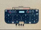
I’m working on a 2385E and the original filter capacitors were leaking, given that they were in dire need of replacement, I purchased a brand new PCB board on eBay and for upgraded 8200 UF 100V capacitors.

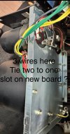
Unfortunately, this board came with no instructions. Does anyone have experience with this?? If so, any pictures I can see where the wiring goes to just double check my work would be a God send of help. This is not an easy process, so I appreciate your help.


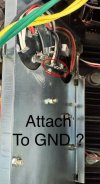
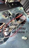
Which wiring am I disconnecting from the ground strap on the chassis to connect to the GND on new board ?

Please see pics and my current work and please help / let me know if this is correct. I greatly appreciate it. Thank you.
 

Attachments

  • IMG_3612.jpeg
    IMG_3612.jpeg
    120.9 KB · Views: 24
  • IMG_3610.jpeg
    IMG_3610.jpeg
    95.1 KB · Views: 25
  • IMG_3613.jpeg
    IMG_3613.jpeg
    87.5 KB · Views: 26
  • IMG_3614.jpeg
    IMG_3614.jpeg
    98.2 KB · Views: 25
  • IMG_3616.jpeg
    IMG_3616.jpeg
    128.3 KB · Views: 24
  • IMG_3618.jpeg
    IMG_3618.jpeg
    129.7 KB · Views: 24
Register to hide this ad
I guess this is the correct way

View attachment 3499167
I definitely see what you’re saying, but the ground wiring from the original ground strap needs to be removed and then soldered to this board where it says GND, so it’s like the original ground plate is actually not being used any longer.

My thought is that the metallic mounting holes that this PCB board are acting as a ground, and as we now inserted the ground wiring into this board it makes a connection in that sense…, would that work / be a possibility ?
 
The plate was used for the convenience of connecting two capacitor leads and all other ground wires in one place. If you can do this without using a plate then you don't need it.
 
Are the 2 ground ports marked on your board already connected with each other by a trace on the other side of the board?
 
Last edited:
The plate was used for the convenience of connecting two capacitor leads and all other ground wires in one place. If you can do this without using a plate then you don't need it.
Exactly my question / thoughts :)

So, I just set my multimeter to continuity, took one screw, affixed the board to the chassis and I get continuity so that means that the metallic PCB hole on this board acts as a ground. In assumption that the now rerouted ground wires that are now soldered to GND on the board should route to the PCB holes and then give ground as well.

Just wanna confirm before I put it all back. I’ve been pulling my hair out with this all day long.. LOL no instructions / input on design sucks ..! Anyways. Thoughts ?

Really appreciate your help.
 
They are shorted, so if you connect all the ground wires (that were previously connected to the plate) to these 2 pins, then these 2 pins will act as a common ground.
 
They are shorted, so if you connect all the ground wires (that were previously connected to the plate) to these 2 pins, then these 2 pins will act as a common ground.
No traces are shown on this board at all which sucks. Can’t see where they follow.
 
Another option is to just
Make sure only these 2 are shorted but not others, then you are ok.
Those run from the amplifiers molex connectors which I’ve disconnected to get extra slack when I removed the transformers sub-chassis. I just plugged one back in to do a quick little test, so I went with my multimeter on the one chassis screw on the PCB board and then went to the GND on the PCB board where those wires are soldered and I got continuity so this is a good sign !

I also noticed and did another test that there is no other continuity running through the positive and negative leads on that board. This concludes that the PCB board metallic screw holes Do indeed have traces to the GND on the board and I can move forward with this Restoration. Thank you so much !!
 
Back
Top Bottom