• The move to the new server is done. There are some software and database maintenance updates in process. This has us passing the hat around to help out. We appreciate any donations. Seriously, even a dollar helps. The payment page may be found here - https://www.audiokarma.org/support.html

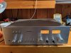
Help me troubleshoot Rotel RA-713 integrated amp

ViperZ

Well-Known Member
Hi all,

I have this integrated amp. The amplifier circuitry is fully working - I can trace sound all the way to the relay contacts, DC offset is a couple of mV on each channel. The relay works too - I can trigger it externally.

The whole protection circuit is turned off - D903 is not biasing at all, no current going through relay coil, so I get 0V across coil - 30V on each side of coil relative to ground. All transistors and diodes in the circuit check out with junction test. Q904 has weird voltages on it too.

Thank you.
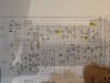
IMG_20190419_115822.jpg
 
Register to hide this ad
Voltages on Q905 and Q906? ACV on pin AC7?
Craig

AC7 = 5.6 VAC. Q905 is all zeroes. Q906 has 30V on collector, 0 on base and emitter.

Q904 is weird = 60.5V on collector, 30.5V on emitter, 30.5V on base. Looks like voltages on the SM are incorrect - how can it have 30.5V on emitter and 13.1 (131?) on emitter - EB junction is always 0.7...
 
Last edited:
Hm, Q902 has 0 on base and emitter, and -7V on collector. Collector is supposed to be ground??
 
Collector should be a bit less than -12VDC by way of the Zener, D902. There's no tie point on the collector line to ground. The emitter is grounded thru the 470 Ohm resistor.
 
Oh, you're saying these lines from collector and r910 are not connected?

To turn on this trabsistor q902, I would need BE junction to have a voltage across it, so Base voltage should be below zero?

My understanding is that q901 is on, since I have 0.5 on EB junction, but for some reason q902 doesn't turn on.
 
Q901 and Q902 are the output DC detectors and should be off unless there's a problem. The base voltage of Q903 will tell you if it's in DC protect, should be 0VDC. If Q903 is ON it will kill the drive for Q906. Have you measured the DC offset of each channel before the relay contacts?
 
DC offset on each channel is 2-3mV.

Ok, so q901 and 902 should be off to keep q903 off. But q903 should have 5.6v on collector, and I have 0.09v. r917 is good at 56k, and has 30v on the other side.
 
Pulled q905. All voltages are within normal on q903, relay engaged. Tests ok on my transistor tester... Would couple be wrong?
 
The -DC voltage developed by D907 and C912 is supposed to hold Q905 in cutoff with -1.5VDC on the base any time power is applied. Once power is turned off that - supply collapses instantly and de-energizes the relay. Before you had 0VDC there, check in that area if you think Q905 is good. Maybe C912 is dead causing too low -DCV.
 
I replaced q905 with ksc1845. I also replaced c912, but it measures ok on the multimeter. Everything seems to work ok. I'll keep monitoring it for a bit, since I have to fix a couple of other small things in this amp.

Q903 and q905 voltages are all correct now.

Thank you so much for helping me to save this amp!!
 
Last edited:
Been listening to this amp for a few hours now. Right channel would disappear after half an hour. Touching most controls would restore it right away. I soaked controls in deoxit twice - no go. Measured resistance of relay contacts - 26 ohms on one side, 1 ohm on the other. Swapped the relay, hopefully that's it lol.
 
Back
Top Bottom