• The move to the new server is done. There are some software and database maintenance updates in process. This has us passing the hat around to help out. We appreciate any donations. Seriously, even a dollar helps. The payment page may be found here - https://www.audiokarma.org/support.html

HELP NAD 3020 1 dead channel in power amp

Northnmonkey

New Member
I was stoked to pick this up at the dump the other day.... but of course it's never that easy is it. Through the left channel it sounds really nice, clean faultless. The right channel is totally dead - nothing at all.

I connected the pre amp up to another amp and both channels work perfectly and sound clean, I also swapped all the fuses around and it was still the left channel so the fuses must be good. The issue must be with the left channel in the power amp.

I also noticed that 1 transistor that screws onto the board with the 4 flat metal cap things (BD139) was visibly totally fried. Went to the electronics shop and soldered a new one in tonight thinking that had to be my problem - still dead right channel. I'm pretty amateur at soldering so maybe thats my problem, but I have checked and double checked and my soldering all looks good (ugly but solid enough) and does not look to be any shorts or anything.

Im pretty new to all this electronics so you might have to bear with me a little. I have spent much time on here reading the forums and have tried all the things I can find so far but now I'm all of ideas.... I have a multi meter and a (very) basic idea on electrics.
 
Register to hide this ad
Do you have a multi meter? Preferably a digital multi meter that can test diodes and transistors.
 
I have an el cheapo digital multimeter and only the most basic knowledge on how to use it so I don't know if it will test diodes and transistors
 
If your multimeter can test diodes, then it can also test transistors. (Same function)

If you plan on getting into electronics repair then it's always nice to have a good one. If you are willing to spend the money then you will be set with a fluke 115 or fluke 117, though a friend recommended this one.

http://www.amazon.com/Velleman-DVM850BL-Hold-Function-Backlight/dp/B00068U24A


Here are some videos on testing transistors.

Are you aware of what output transistors are?
 
Thank you for that.... the first problem I have though is knowing where to start - i don't even know which part is the preamp and which is the power amp. I don't know if the transistor that I already replaced is part of the preamp - in which case I must have done it successfully because it works, or if it is part of the power amp then almost definitely I didn't get it right and that's why it still does not work.

If someone could point out which board is the power amp and which is the preamp then I have a starting point. Also can you test transistors while still on the board?

This is the transistor that is clearly fried that I replaced, I will upload one of the replacement - and my poor soldering tonight when I get chance.
20160520_162359[1].jpg
 
When some one says they have one dead channel, then one of the first things I would think about would be the output transistors. In most Recievers the preamp and other sections of the devise would be separated by different circuit boards but overall it looks that this amp is all on one big board.

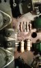
Circled is what looks like the amp section in my opinion. The four large circular things Circled in the green are the output transistors, sometimes referred to as "outputs". Post more picutires of the amp. Do any of the capacitors look bulged? image.jpg
 
When some one says they have one dead channel, then one of the first things I would think about would be the output transistors. In most Recievers the preamp and other sections of the devise would be separated by different circuit boards but overall it looks that this amp is all on one big board.

Circled is what looks like the amp section in my opinion. The four large circular things Circled in the green are the output transistors, sometimes referred to as "outputs". Post more picutires of the amp. Do any of the capacitors look bulged? View attachment 737098

That is actually somewhat different to the insides of mine. The board with the 4 circular things is the same, and the small square transistor on the right that attaches to the main board is the one that fried and was replaced. If this is part of the power amp I guess I either replaced the transistor poorly, or it also fried one of the other components at the same time. Everything else in there looks good to my untrained eye - no bulging caps or anything obviously untoward.
 
There are a few different models of the NAD 3020. So identify your specif model. Then you can download the correct service manual from this site. You need to make an account to download these manuals, but it's free and easy to make one.

http://www.hifiengine.com/manual_library/nad/3020.shtml

Some threads that describe a similar problem.

http://audiokarma.org/forums/index.php?threads/nad-3020-stereo-amp-no-sound.151475/
I'm 99% sure mine is the basic 3020 (not the B or I), I will try to put up some pics of the inside later today once i'm hone.
 
OK, so got some pictures20160525_195152[1].jpg insides

20160525_195200[1].jpg Output transistors? including the new BD139

20160525_195200[1].jpg Smaller circuit board at the back

20160525_195336[1].jpg My poor soldering job - The circuit board was pealing slightly so I bridged it with a piece of wire just to make sure it was connecting properly.
 

Attachments

  • 20160525_195219[1].jpg
    20160525_195219[1].jpg
    83.6 KB · Views: 21
i would first get the thing cleaned up a bit then see if there are anymore burned resistors like the 2 i see on the picture .then test the other transistors in that blown channel
 
i would first get the thing cleaned up a bit then see if there are anymore burned resistors like the 2 i see on the picture .then test the other transistors in that blown channel

Thanks for the reply, if you can see 2 burned resistors could you give me an idea of where they are because I'm not sure what I am looking for? .... I can't see anything obviously burned, although admittedly I'm not sure what I'm looking at....... also can you test transistors in situ while on the board? or do they need to me removed? cheers.
 
in you first picture the 2 cooked resistors are above the blown out transistor .
you can test if transistors are shorted in circuit then pull them if so . its best to just pull them out and test or simply replace in the first place really though .
make a note of the bad ones and where they came from to make later diagnosis easier .
resistors might be bad even if not obviously burned like those in the pic .
 
For cleaning it I would first get some blow off duster. I believe it's sold at the "dollor store" if you have one in your area or ace hard ware. This will get all of the loose dust out then I would break out the q tips. Most people use isopropyl alcohol with the q tips and scrub the circuit boards. I personally prefer spraying deoxit D5 on the q tips and scrubbing because it doesn't leave as many white streaks.
 
.....in you first picture the 2 cooked resistors are above the blown out transistor... .
.

Good eye!!

For a unit that dirty, I break out the vacuum cleaner and soft brush. That way all that crap doesn't end up flying all over the place. Cleaning things up will give you a better working environment to desolder/solder.

That's a good piece. You shouldn't skimp on the work :thumbsup:
 
Ah... ok now I look at those resistors I can blatantly see they are burned - amateur eh...... Looks like I have some work to do, will try and clean up, replace those resistors, see if it works, and then carry on testing. Might take me a while to get this stage done but will update when I do.

Thanks everyone!
 
Ok, next installment...... I cleaned up the PCB, removed the burned resistors and took them to Jaycar (our radioshack) to get replacements. Couldn't find the right size but they said that going up to 1/2 watt would be fine as they are the same ohm.

Put in the new resistors and now my right Channel is alive!!....... but all it does is HUM loudly. No music coming though at all, just a loud hum, anyone any ideas where to start? Could it be the bigger resistors? or something else?
20160529_174008[1].jpg 20160529_174025[1].jpg 20160529_174251[1].jpg
 
Back
Top Bottom