• The move to the new server is done. There are some software and database maintenance updates in process. This has us passing the hat around to help out. We appreciate any donations. Seriously, even a dollar helps. The payment page may be found here - https://www.audiokarma.org/support.html

Help needed with my Sansui 9090db

lopezluna

Active Member
Hello everyone. I recently purchased a sansui 9090db receiver in working order. After a month of owning it I decided to do a restoration on it. I started with the F-2625 power supply board, caps, transistors. Tested on dim bulb and all good. I then moved on to F-2624 Driver board and replaced caps, fusible resistors, transistors, and the 4 pots for dc and bias adjustment. Tester on dbt and all good so I adjusted dc offset and bias without dbt. Moved on to F-2653 Equalizer circuit board and replaced capacitors and tested with dbt and all good. Moved on to F-2619 Power supply board RF section and replaced the electrolytic caps 3 transistors and 1 diode. Tester on dbt and all good. Next I moved on to F-2657 Power relay circuit board and replaced the capacitors, two fusible resistors and 4 transistors tested on dbt and bulb stayed bright. Oh No.. I removed the F-2624 driver board and powered it on dbt and bulb dimmed and came out of protection. I noticed that when driver board is connected the light on front of receiver will Not light up and does not come out of protection. As soon as I remove driver board all lights work again. I replaced the 4 transistors with the old ones and still not working. Any ideas of what is causing this problem when driver board installed and connected no lights come on and it won't come out of protection? I have restored 3 pioneer sx-1050's and one pioneer sx-1010 before. I do not have a scope or any fancy tools like that. I now wish I would have left it as it was because I have no idea where to start troubleshooting this problem. Any help will be greatly appreciated. Thanks lopezluna. For those interested Serial # 817092804
 
Register to hide this ad
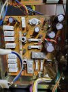
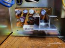
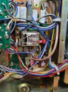
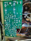
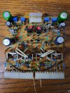
Here are some pictures of the boards I have worked on
 

Attachments

  • 20240505_205002.jpg
    20240505_205002.jpg
    151.7 KB · Views: 20
  • 20240505_205012.jpg
    20240505_205012.jpg
    153.3 KB · Views: 19
  • 20240505_205018.jpg
    20240505_205018.jpg
    123.6 KB · Views: 18
  • 20240505_205028.jpg
    20240505_205028.jpg
    122.4 KB · Views: 17
  • 20240505_205054.jpg
    20240505_205054.jpg
    162.9 KB · Views: 20
Starting with the last board you serviced, check capacitor polarization. It's easy to put one in wrong. Check for pinched wires.
It does sound like whatever mistake you made on the F-2757 power board, may have damaged the driver board.
The error on the power board will need to be corrected before you can plug the driver board back in.
 
Starting with the last board you serviced, check capacitor polarization. It's easy to put one in wrong. Check for pinched wires.
It does sound like whatever mistake you made on the F-2757 power board, may have damaged the driver board.
The error on the power board will need to be corrected before you can plug the driver board back in.
I did take pictures of the capacitors orientation before replacing them but I will check cap orientation again, It sure wont hurt. I will also check for pinched wires and continuity of any suspect wires. I might re-install the old capacitors just to see if anything changes. Thanks tutor_turtle:
 
If I understand your situation, it was working properly before you started and continued to work properly until you serviced the protection board F-2657. You probably have a solder bridge on that board shorting the audio output.

The L & R audio signal runs from the bottom of the main power supply board to the protection board through a blue and a gray wire. On the DBT and everything installed measure the DC voltage between each of these wires and chassis ground.

- Pete
 
If I understand your situation, it was working properly before you started and continued to work properly until you serviced the protection board F-2657. You probably have a solder bridge on that board shorting the audio output.

The L & R audio signal runs from the bottom of the main power supply board to the protection board through a blue and a gray wire. On the DBT and everything installed measure the DC voltage between each of these wires and chassis ground.

- Pete
I will measure DC voltages exactly as you instructed this evening when I get home from work and I will report my findings. Thanks LBPete
 
If I understand your situation, it was working properly before you started and continued to work properly until you serviced the protection board F-2657. You probably have a solder bridge on that board shorting the audio output.

The L & R audio signal runs from the bottom of the main power supply board to the protection board through a blue and a gray wire. On the DBT and everything installed measure the DC voltage between each of these wires and chassis ground.

- Pete
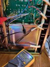
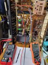
Here are my dc voltage readings from grey and blue wires to chassis ground with everything connected and DBT. Righ channel blue wire & ground I was able to adjust dc offset within specs 0mv-5mv dc fluctuating. Left channel grey wire to chassis ground very high. Some adjustment but still almost 500mv dc
 

Attachments

  • 20240506_181316.jpg
    20240506_181316.jpg
    153.8 KB · Views: 11
I checked for solder bridges on relay board and don't see any. Also capacitor orientation is correct. Verified with the pictures I took before replacing caps
 

Attachments

  • 20240506_193322.jpg
    20240506_193322.jpg
    143.2 KB · Views: 9
With all boards and everything connected to DBT bulb stays bright and receiver in protect mode and None of the lights work. With Driver board removed again connected to DBT lights work and it comes out of protect mode.
 
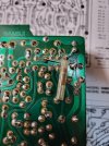
I fixed it guys. I did a continuity check on the F-2624 driver board and my readings were way different between the two channels. I removed and tested every transistor on the left channel and they were all good. I then looked real closely at the traces. There was one that suspect. I did a repair and now I was able to adjust dc offset and bias while still on DBT. I did adjust bias to 15ma while on dbt. Plugged it in straight to wall power and adjusted dc offset again and bias. All lights work again. I'm back in business. Thanks to those of you that made suggestions of what to look for. I attached a picture of the repair I made to the board to repair bad trace. Thanks again guys
 

Attachments

  • 20240507_205253.jpg
    20240507_205253.jpg
    141.7 KB · Views: 31
  • 20240507_213952.jpg
    20240507_213952.jpg
    180.6 KB · Views: 30
Thanks EastPoint. I am sure I caused the damage while repetitively removing and re-installing the board. I must have bumped the bipolar cap on top left of board and that was enough to cause a break in the trace visible to me only with my magnified glasses. Now I can proceed with the rest of the restoration
 
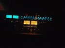
@LBPete Thanks for leading me in the right direction towards finding the problem. Who would have known it was going to be a broken trace on driver board right next to the solder side of a cap on a board that had already been finished and tested good. I appreciate your help. I already did all the boards except for the Dolby board and am thinking about leaving it alone as it is working as it should for now. Opinions on whether I should go ahead and continue with Dolby board or leave it alone for now. Thanks again LBPete and everyone else who helped me. Ben
 

Attachments

  • 20240515_231410.jpg
    20240515_231410.jpg
    39.6 KB · Views: 1
  • 20240515_224908.jpg
    20240515_224908.jpg
    77.7 KB · Views: 1
Back
Top Bottom