• The move to the new server is done. There are some software and database maintenance updates in process. This has us passing the hat around to help out. We appreciate any donations. Seriously, even a dollar helps. The payment page may be found here - https://www.audiokarma.org/support.html

Help Needed With Pioneer SA-7800 Repair

Mbz, good news to report.

I reinstalled the rebuilt power supply board last night and started it up without the power amp board installed and with a dim bulb tester attached.

The power supply board operated perfectly and was generating the correct voltage (around 48V) and there was no short. The bulb when bright for just a second and then completely dark.

This means the problem is on the power amp board for use.

I am going to lower the trimmer resistance as low as possible tonight, check the diodes one more time, and then give it another run.

Worse case scenario, if something doesn't work, at least it will give me a clue as to where the problem on the board is.

I will not install the outputs yet and will report back tomorrow.

Let's hope for the best.
 
I adjusted the trim pots and made sure the resistance was close to zero, per Mark's advice in another thread.

I then reinstalled the power amp board. R60 started to overheat immediately. Obviously haven't solved the problem. The lightbulb also didn't dim like it did with no power amp board installed.

Back to drawing board.
 
My approach is get the amp to a point where you can troubleshoot
getting consistent/reproduceable results and then track down the
fault. Component testing is a little unreliable.

Have you tried a low wattage bulb in the DBT?
Do components still "smoke"?

With outputs removed, the 26V on Q24, Q26 b/c/e is a significant symptom.
Extremely important that you note the correct sign.

Cause of the unbalanced (26V) could be a transistor (eg, Q24) failing
short c-e or a short in D18 or... The other scenario is a component fails
open so it does not provide the intended negative voltage to counter
voltages from the positive half of the amp.

With outputs removed power up on low wattage bulb (30W?)
Check power supplies, pins 1,2 9,10,13,14 (on power amp board)

Re-measure Q24, Q26 b/c/e with this reduced wattage.
Measure Q6, Q10 b/c/e Vdc to ground.
 
I feel pretty dumb. I had Q23 and Q25 switched and Q24 and Q26 switched. This must have happened when I installed the original Toshiba transistors and then I carried it over to the new ones. I can't believe it took me two weeks to catch this. It explains everything.

I'll let you know if it works when I reassemble everything tonight.

I want to scream.
 
Last night I put it all back together (except outputs) and had a moment of utter happiness when the speaker relay clicked and no smoke appeared. It appears stable without the output transistors installed.

Here is the question:
I started to turn up the resistance on the trimmers (all of which had been set to minimum resitance, i.e., minimum bias) in accordance with the service manual. But although I could feel the increased heat from the channel as I turned it up, the DC voltage across TP1 and TP2 stayed at zero. I was scared to keep turning it up given that I started to feel more heat, so I stopped and turned it back down. This may just be my paranoia, but do I need to reinstall the output transistors before I set the bias in accordance with the manual? I ask because Mark suggested that the bias could be set with them removed.

It may just be that I needed to keep turning up the resistance, but did not want to take the chance given how fragile these NSA amps can be.

Any help or suggestions would be greatly appreciated.
 
Okay, so the right channel is testing perfect and is stable with the correct bias and virtually no dc offset on the speaker outputs. Huge win so far.

Left channel is semi stable, but I'm getting rising dc offset going from 500mv and move up past 1 V before I shut it down.

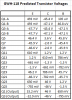
I'm going to check the internal voltage on that board against the chart above to see if I can find any problems, but any thoughts would be appreciated on potential causes. I already switched out the output transistors, so they are not the problem for sure.
 
Left channel is semi stable, but I'm getting rising dc offset going from 500mv and move up past 1 V before I shut it down.
Typically, dc offset is/can be caused by the differential pair, 5 pin transistor Q1. I would be against switching with Q2. Suggest test
using 2 TO-92(?) transistors (KSA992?). These should be closely matched hfe and Vbe.

1V is starting to get high so might point to problems elsewhere, suggest check for voltage stability at Q1 base(R57?) and
Q3 base (R59)
 
So here is where I am: Both channels start up with voltages that are fairly close to where they should be.
However, the voltage on the right channel starts to drop such that within a minute the voltage on the base and emitter on Q23 turn negative. The opposite happens on Q24, the voltage on the base and emitter rise. These symptoms cascade across both channels, with voltages rising or falling at a number of text points. The change seems like it would go on forever if I didn't shut the amp down.

Any ideas? All the voltage from the power supply are stable and correct (the gray wire that goes to point 5 is 1.6V instead of 1.1V, but I doubt that is the issue).

The fact that the identical issue is affecting both channels leads me to believe this is not one resistor or diode. Remember that all the silicon is new and the resistors and diodes were all checked. The relay is also new.
 
Q23 and 24 base should both be about +1.2Vdc, so why is Q24b initially negative?
Monitor Q6 Vbe during start up.

Pin 5 should be -1.1Vdc. +1.6Vdc would be of concern, the protection circuit is
common to both channels.
 
Back
Top Bottom