
• Please note that Audiokarma will be offline briefly for updates early on Monday morning, September 28th.

Help recapping Rectilinear III's?

judgeschreber

Well-Known Member
I'm starting a recap project on my second pair of Rectilinear III's, and I've run into a problem. They have a different crossover than the pair I've already done, and one of the caps doesn't have a value printed on them. They are black with red ends, cylindrical, about an inch long and 1/2 inch in diameter. They are only marked "XMC," which doesn't correspond to any common code I could find on the net.

They tested at 91 uF and 104 uF, but they are almost 40 years old, so I'm not sure what to do about buying new ones. I could just go with the reasonable choice (100uF), but according to my calculations that would make the midrange roll off at around 100hz, which seems quite low to me (and I've read elsewhere on the net that they are supposed to roll off at 500uF, although I'm not sure if that is completely true).

The other pair I did recap had a completely redesigned crossover, and used 60uF caps, but the xover was so different that I'm not sure whether I should take that into account.

Anyone have experience with Rectilinear III crossovers that could give me a word of advice on what the value of these caps should be?

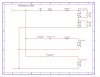
Any super crossover experts want to check the schematics I've attached and give me an educated guess?

Anyone else want to chime in?

The first attached schematic (Rectilinear III 1969) is the pair I want to recap, and the cap I'm interested in is in the midrange circuit and marked "XMC." The pots are variable resistance from 0-14 Ohms (measured .1-14.6 Ohms), and were sometimes simply replaced with an 8 Ohm resistor in the midrange path. The chokes are marked 101 and 201, but I'm unsure what their values are. The second schematic (Rectilinear III 1971) is the updated crossover for comparison's sake. I assume the crossover points are the same, but I can't be sure.

I know it's a shot in the dark, but if anyone can help me out, I'd be very very thankful.
 

Attachments

  • Rectilinear III (1969).jpg
    Rectilinear III (1969).jpg
    44.7 KB · Views: 160
  • Rectilinear III (1971).jpg
    Rectilinear III (1971).jpg
    46.3 KB · Views: 150
Register to hide this ad
The 1969 version looks like an excellent candidate for bi- or tri-amplification with a passive line level crossover. One could separate and bring out the leads to each of the speaker groups (woofer, mid, and tweeters) then experiment with the XMC values until it sounds right.

I'm sure that's what the original designer did in the first place.

BTW, I picked up my set of Rectilinear IIIs from OnePixel last night. I expect and hope that they are the 1969 version too. After a short listen, I turned the tweeter level control full up and it sounded much better. I may back down a bit. Also think that spikes would help tighten the bass. My set has four metal knobs on the bottom but aren't level on my concrete garage floor - maybe a single spike in the front so I can tilt it back a tad.

A midrange going down to 100 Hz doesn't sound all that bad to me. These look like first order crossovers (but I'm no expert) and so roll off on a gentle slope. The Fostexs and Lowthars run a similar sized cone as a full range but only get down to 50 to 70 Hz even with transmission lines. That would also relieve the woofers from higher frequency duty.
 
I am not familiar with Rectilinear III's; but, the 1969 version schematic shows. . .

Woofer:

1st order band pass filter. It has a coil (only) that says it's a low band pass filter. No idea where without a mHy figure for it. But, speculation says it should be choked somewhere around 200Hz. (6.4 to 5.8mHy)

Midrange:

1st order band pass filter. Could be either a normal band pass, or a narrow band pass. A standard 1st order band pass would be 200Hz with a 100µF cap. A 1st order narrow band pass EXAMPLE would be 180/2000, requiring a 100µF cap and a .7mHy coil. Plus, the 14 ohm pot allows you to make some frequency changes to the mids by varying the resistance.

Tweeters:

1st order high band filter only. Two sets of drivers, which are most likely all 8 ohms since you have both parallel and series. That will still give you 8 ohms across a group of four drivers. However, with the 2 ohm resistor added the effective load is now 10 ohms. So, the crossover point is around 8KHz; and the 14 ohm pot again gives you a frequency control adjustment by varying the resistance. However, it seems odd that a design would have all four set for the same frequency response.

. . Falcon
 
Congrats on the new Rec III's! From what you say it sounds like they only have the one tweeter control, which from what I understand means that they are the earlier version with the first order parallel crossover. I think, based on what I've seen, that this means you have Jensen woofers rather than the later look-a-like CTS woofers, which are in my 1971 Rec III's. The other main difference between the two that I saw was the port diameter--a lot smaller diameter on the earlier version. If you look on another post I had about the differences in Rec III's (not including the lowboys and the IIIa's) I give a lot more details on what I've observed--I'd love it if you could add to the knowledge too!

Thanks for the suggestion about using the passive line level crossover. I suppose what you suggest is the best way to go, but unfortunately I don't have the equipment to perform that sort of text.

I think right now I'll just replace these with some 100uF electrolytics as a temporary fix until I can confirm the proper values. If you ever end up opening yours up and taking a look, I'd be interested to hear what you find out.

Edit: btw, I also turn my mid and tweeter knobs up quite high on these speakers. I find them a bit muffled otherwise.
 
FalconEddy: Thanks for the reply. You sound really knowledgable about this. I have a couple questions, though.

Wouldn't the variable resistor change the crossover frequency? The midrange pot was substituted for an 8 Ohm resistor in an earlier design (I have a mismatched pair--one has the midrange pot, the other has a resistor instead, but they both have the same "XMC" cap), which makes me think the designers assumed a "normal" position on the pots as adding 8 Ohms resistence. Wouldn't this make the bandpass around 100 Hz, instead of 200Hz?

Also, forgive my ignorance, but I don't know what a "narrow band pass" is all about. That's probably one for google, though. It's funny but I find the best online knowledge written in clear, easy to understand language is about car audio. They seem to have the best, down-to-earth sites for the tinkerer, but not the expert.
 
judgeschreber said:
Wouldn't the variable resistor change the crossover frequency?

Absolutely. That's why I said the 14 ohm pot would allow you to make some frequency changes by varying the resistance.

judgeschreber said:
The midrange pot was substituted for an 8 Ohm resistor in an earlier design (I have a mismatched pair--one has the midrange pot, the other has a resistor instead, but they both have the same "XMC" cap), which makes me think the designers assumed a "normal" position on the pots as adding 8 Ohms resistence. Wouldn't this make the bandpass around 100 Hz, instead of 200Hz?

It's possible, but I don't know where the 'normal' would be labeled. If it's about half way, it's 100Hz. If it's all the way down, it's 200Hz. But, that's a really low crossover point for a mid. What size is it???

That analogy would also put the tweeter crossover around 4.5KHz.

But, that throws out the narrow band pass arrangement also, because now it's at least 50 times (decades) different.

Based on your cap measurement values, it simply makes more sense the way I first presented it. It allows the woofer to be choked around 200Hz, and the mid to pick up from close that point.

judgeschreber said:
Also, forgive my ignorance, but I don't know what a "narrow band pass" is all about.

A narrow band pass filter allows a low point roll off, and a high point roll off; whereas a low pass filter only allows to lows to pass, and a high pass filter only allows the highs to pass.

. . Falcon
 
Thanks for your responses. If I can pry a bit further, for the sake of educating myself, I'm still unclear on a couple of things. (Anyone else also please feel free to chime in).

First off, the mid is only 5", but it is a full-range driver (one of those Philips whizzer-cones). Since it's full range, I assume that means it is capable of crossing over pretty low.

Thanks for explaining "narrow band pass," but to me that sounds the same as a "band pass." Is there a difference between these?

The variable resistance thing confuses me a bit. It makes sense that adding resistance would decrease the output a bit, thus making a good way to control the tweeter volume. But, if it also changes the crossover frequency, wouldn't that screw up the whole voicing of the speaker? For instance, if the tweeter starts crossing over at a different point, but the midrange is still choked at the same point, wouldn't there be gaps and peaks in the frequency response?

Finally, is the change in resistance the only thing the pots do? I ask because only one of the speakers has the midrange control, so I'm thinking of bypassing the midrange control with a resistor in the other one to match. Right now the one without a midrange pot has an 8 Ohm resistor in place of it, but I've noticed on my other pair of Rectilinear's that I like to adjust the midrange pot almost all the way up, so I'm considering replacing the 8 Ohm resistor with maybe a 1 or 2 Ohm resistor, and replacing the pot on the other speaker with the same thing. Does this sound like a good plan?

Thanks for the help--I'm trying to educate myself with all this fascinating stuff, and I really appreciate the patience of the more knowledgable and experienced members here.
 
I've been toying with the idea to build a single Rectilinear just to check how it sounds.Nothing fancy,so simple leftovers of chipboard will do.I have all the drivers except for the original woofer,but a similar type probably won't change the overall sound too much.
Now to the problem.After checking the 1971 xover schematic,I must say I was puzzled.Something was wrong,I'm afraid.What we have is a three-way series type,so I redraw it after looking at the photos of actual xovers.It took some time,I admit that,but now it all fits-the pots work as they should-and they actually almost even work as "constant impedance" pots!Much better than the 1969 version.
Take a look and let me know what you think!
 

Attachments

I see. . . The difference in the two schematics is that you have the 201 choke parallel to the 101, whereas mine were (mistakenly, apparently) in series with the second choke.

Good catch!
 
Ok, I've looked more carefully, and you definitely fixed the right-hand side of the schematic. yours is more elegant, it adds the series connection between the two pots, and it corrects the orientation of the pots (my schematic was made before I learned how to represent pots in a schematic!).

However, I think I may have to disagree with you about the left side of the schematic. This picture from the AK archives shows the 201 choke (on the left) is wired in series with the larger cap, and in parallel to the smaller cap, and then in series with the 101 choke, like on the schematic I drew.

http://audiokarma.org/forums/attachment.php?attachmentid=31950&d=1164663914

The larger black cap comes directly off the + terminal, and into the first terminal of the terminal strip. That 1st terminal also goes to the 201 choke (red wire), and the smaller cap (candy-striped). Both the choke and the smaller cap then go to the 3rd terminal on that same terminal strip (red wire from choke is barely visible underneath terminal strip). From there, a second wire goes to the 101 choke on the right (black wire).

So, looking at that photo I'd say my original schematic was correct on that one account.

Please correct me if I'm wrong.
 
Back
Top Bottom