• The move to the new server is done. There are some software and database maintenance updates in process. This has us passing the hat around to help out. We appreciate any donations. Seriously, even a dollar helps. The payment page may be found here - https://www.audiokarma.org/support.html

Help Wanted Biasing a Lafayette LR-3500

Isaac C.

Cat Hoarder
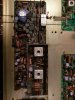
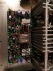
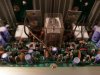
Hello everyone, I am new to the AudioKarma forum, however, I have been viewing the site for a few months now. I am also new to vintage audio equipment, having just gotten into the hobby last fall. Anyway, I acquired a Lafayette LR-3500 a few weeks ago on eBay for $70 in working condition. Since I am new to the hobby, I performed a basic servicing (dusted the inside with canned air, sprayed the pots with DeOxit, visually inspected for any bad caps, and cleaned up the exterior). I have been learning how to further service vintage equipment and today I checked the DC voltage offset on both channels. The multimeter I have is very basic so I set it to 2v as that is the lowest setting. With no input, and volume turned all the way down, the right channel was reading ± .002v and the left channel was reading roughly - .015v. I know this is not much, but I would like to adjust it if possible. The problem is that I am unable to locate a service manual for the receiver so that I know what variables resistors to adjust and the offset specs. On one of the circuit boards I located four variable resistors, RV201, RV202, RV203, and RV204. I am not sure if these are the correct ones, I am not going to adjust anything until I find out for sure. Also I would like to check the bias for each channel, but am not sure how to do so. Any help or advice would be appreciated. Attached are photos of the inside of the unit.
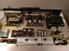
IMAG0294.jpg
The four variable resistors are on this board on the left.
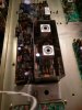
IMAG0299.jpg IMAG0296.jpg IMAG0297.jpg IMAG0298.jpg
Also what are the two pins besides the white resistors above the variable resistors
 
Last edited:
Register to hide this ad
On one of the circuit boards I located four variable resistors, RV201, RV202, RV203, and RV204.

That board is associated with the tuner for sure - the FM IF and MPX sections, at a guess. Those adjustments are not for your DC offset or bias, and to be brief, you probably don't want to touch them.

The board with the white resistors and two variable resistors is the power amp board. It would appear that there is only one adjustment per channel. They are probably for bias, but I can't be certain.

I'm not sure what pins you're asking about. If they are the ones with wire wrapped around them, they are, well, wire-wrap pins. Looks like they might connect the output transistors and/or thermal compensation devices that are mounted on the heat sinks.

If this piece was on my bench and I couldn't find the spec for bias current, I'd set it to 20mA. The general technique would be to measure that current indirectly, by measuring the voltage across one of the white resistors. I can't see the value of the resistors, but let's say for example that they are 0.5 ohm. Then the desired voltage is 20mA times 0.5 ohm equals 10mV, or 0.010V.

HTH, and welcome to AK!

chazix
 
Thank you for the response, I think the two variable resistors measure bias because when I was measuring the voltage from the left channel output, I turned it slightly and it did not change the voltage reading, so I turned it back to the the original position. Maybe I misunderstood, but were you saying to measure the current or voltage across the white resistors. Also does it matter which probe of the multimeter goes on which end of the white resistor. Thanks again.
 
I think I figured it out, took me a minute to think. Basically you are reversing the equation so that current = 10mv/.5ohms. So measuring indirectly, Im looking for 10mv as close as possible across the white resistor. Is that correct?
 
I believe I have the idle current set now. I measured the voltage across the two outer resistors. The voltages to begin with were -14mv on the left channel and - 8mv on the right channel. I assume I had the probes clipped on in reverse order since the initial reading were both negative. I had them clipped red on the front and black on the back. Anyway, they are both measuring at -10 to -11mv on both channels. Just curious, since this power amp board does not have adjustments for DC offset, why is that the output voltage on the speaker terminals measured -15mv on the left channel and ± 2mv on the right channel? What component(s) would contribute to the variation, sorry for the noob questions.
 
why is that the output voltage on the speaker terminals

Don't know. On an amp with a differential pair of transistors as its input stage, a first-order approximation is that offset is due to mismatching of the transistors' base-emitter voltages. But, that is an approximation, and I don't know if your amp has that kind of input stage.

I'd say the offsets you're measuring would be negligible in most people's books - certainly in mine. On many, many amps with offset adjustment, it would be quite difficult to better 2mV!

Cheers,

chazix
 
There are separate operating and service manuals for the Lafayette LR-3500. Unlike some of Lafayette's earlier receivers/amplifiers, the "adjustment of the main amplifier" (idle current, voltage readings, connection of tester to various points, etc.) is not a trivial exercise.It should be followed closely. Likewise, the service manual has all the AM/FM alignments, IF and IF distortion alignments, FM MPX alignment, plus a number of other alignments, adjustments, board layouts, parts layouts and parts list, schematic, etc. Doesn't look like we ever issued any service addenda or updates in the life cycle of this receiver.
Pete
 
Does anyone have a link for the service manual for the LR-3500? I recently acquired one and want to perform some basic checks. I have downloaded the owners manual from HIFI engine and it does have the circuits laid out which will be helpful. This and the above information should allow a newbie like me to do some items. I haven't even checked the DC offset as of yet however. The ironic thing is I sold a ton of these as my days as a manager for a Lafayette store and now finally own one. This was the premier receiver when I started there and yet at the time could not afford one. I did later buy an LR-9090 which I still own and run. I suppose its because I worked there, but I always felt that their equipment was a great value and performed very well, flying under the radar of other brands.
 
hello everyone, i know that this is an old thread but im hoping somebody could help me here. i have this lafayette lr-3500, after 30 seconds or 1 minute the relay kicks out. dc offset is +38mv on one channel and +40mv on the other. i measured accross the white resistors and it reads -4mv and -2mv. i tested the resistors and transistors on the powerboard and it seems all good. any ideas? thanks
 
I have a LR-3500 on my bench right now. I would suspect a bad capacitor in the amp circuit and when it gets a little warm and charged up its leaking DC through the input and pushing the DC voltage up/down, tripping the protection relay circuit. I believe the value of the input capacitor is .47uF at 25v. My units speaker outputs measure from ground closer to zero, like 10mVs. The emitter current on mine yields a voltage across both .47 ohm emitter resistors of 20mV, which means about 20mA of idle current. I always read across both emitter resistors to get a higher voltage reading for my meter. The math is the same but the meter likes it better, especially if its an older one, like mine. Measure the resistors as a pair with power off, consider their marked value to insure its close to what you measure...to determine if they're defective, then divide the voltage you measure by this value to get the idle current.
Try this test:
With the unit cold, put your meter on chassis ground and a speaker positive, then turn the unit on.
Either channel could cause this, so if you have two meters it would be nice to watch both channels.
Watch the voltage. It should be near zero, especially if speakers are attached. If it begins to drift up or down until the relay trips, then its the power amp capacitors or a bad transistor getting warm and leaky. If the voltage stays pretty constant and the relay falls out, I'd look at the protection circuit itself. Don't use audio during this test, just quietly sit and watch the meter.

I fixed the left channel on my unit, which had bad outputs. I've been hunting a snap crackle pop in the right channel, but so far no joy.
I changed the electrolytic capacitors this afternoon, still no joy. Now I'm looking at transistors again.

I need an alignment proceedure for the FM section, maybe the AM too. It looks like someone just turned things...hard to tell, but some of the goop that keeps things from moving has been broken...
I looked up the chips on the tuner sections and one is unobtainable. If anyone has additional info on tuner alignment on this unit, I'd appreciate it.
It does tune FM, but the signal strength is off and the center meter doesn't track. I haven't tried AM yet and until I get this crackle gremlin evicted there's not much point! HiFi Engine has a user manual with schematic for free download if you'll make an account.
Thanks in advance to anyone and good luck to everyone.
 
Back
Top Bottom