• The move to the new server is done. There are some software and database maintenance updates in process. This has us passing the hat around to help out. We appreciate any donations. Seriously, even a dollar helps. The payment page may be found here - https://www.audiokarma.org/support.html

Help Wiring Dynaco PAS-3 Phono Stage PCB

KCharlemagne

New Member
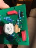
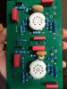
Hello all, I'm wondering if anyone can give some advice on how to wire this Dynaco Pas-3 phono board (this is from ebay / labeled as the PC-6A and seller is not responsive). I have limited experience building simple tube kits, but I can't find a wiring diagram for this particular board, and don't exactly want to start hooking up B+ without being sure of what I'm doing. I'd also like to run this as an independent unit, i.e., I do not want to insert it into a PAS-3 chassis w/ tone controls, but instead want to hook it to an independent power supply and run it as a stand alone phono stage.

Any help would be hugely appreciated. Thanks in advance!
 

Attachments

  • 28124878_2055242878085620_1027699831_o.jpg
    28124878_2055242878085620_1027699831_o.jpg
    38.6 KB · Views: 54
  • 28126509_2055237571419484_1178873060_o.jpg
    28126509_2055237571419484_1178873060_o.jpg
    51.3 KB · Views: 54
  • 28208089_2055242881418953_1301870153_o.jpg
    28208089_2055242881418953_1301870153_o.jpg
    53.3 KB · Views: 53
Register to hide this ad
assuming the numbering matches the original PC-6 board, the PAS assembly manual would be the place to check.

http://www.thetubestore.com/lib/the...aco/Dynaco-PAS-3X-Schematic-Owners-Manual.pdf


One of the tricks with these is that they are meant to work into the stock PAS line stage load. Basically thats the volume control and balance pot, about 190K all told. Get too far away from that and it can affect the accuracy of the EQ curve. It also won't have any drive worth talking about, so this needs to work either into a fairly high impedance input, or you can knock together a simple cathode follower circuit. That would let the preamp work into the right load and be able to feed into basically anything you want. An op-amp or MOSFET buffer would get the job done every bit as well.
 
if you're not replacing an existing board in a PAS 2/3 then you'll need to be able to read
the schematic and trace the board (although the board's stenciled/marked numbering will help).

reason why is that the PAS was pretty complicated for it's day with tape head inputs,
am/fm on one selector, and blend (if I recall correctly). the original selector has NO
modern equivalents. believe me I tried, and had to disassemble one down to parts.

since you are using it for phono then you can eliminate everything. Just be careful, there
are several grounds that need attention. eg the phono ground circuits are not directly
tied to line stage grounds. and your next stage may experience HUM.

review the audio regenesis and dynaco-doctor threads. even audio basics from van alstine
(he offered buffered stages using opamps about 35 years ago), also triodeelectronics,
and the Norman Koren mods. all have good information.

and I'd up the transformer specs, the original pas trafo could not support even one extra
12ax7 both heater and plate currents. you could also a buy a cheap tube voltage regulator
and wire that it, not because it needs it since it's all Class A, but to control any AC
line fluctuations that are multiplied by the pri/sec ratio.

As @gadget73 recommends, add a buffer/CF, if it's tubes use a 6SN7 for TONE.

start with the trafo, go to triode-electronics and look up the specs, then find one that
has better specs, (try all the Hammond, other vendors), then think about redesigning
the power supply. I have found that original pas's over voltage the first cap stage,
which is usually 450v caps, I have seen 470v on these. so go with 500v caps
from JJ or use the voltage regulator. if you are able, there are high voltage regulator
chips, google them to find info.

do note that the heaters were wired in series and used lowered voltages which is
why they lasted all these last 60 years or so. also do not believe the "suburban"
legends about the smooth plate telefunckens being the best.

do a search on ebay for kits or assembled units and look at the PS boards they use,
they are cheap and you simply solder in parts, no design work. I'd stick with
tubed rectifiers but not the limited cheap PAS tubes (12x4 as I recall) use a
5u4 (cheap and enough juice to power a push-pull tube power amp).

since I sense you are not using the corresponding line stage, you can simplify the
PS voltage reductions. if you are not using a VR then I'd recommend using 2 or 5
watt resistors in the dropping circuit.

good luck and post your discoveries - you may be starting a new trend here.

 
Hello,

Thanks to both of you for the replies! It sounds like this might be a little bit more of a project than I anticipated. I'll update as I figure out more about how to do this. Bob, any idea why they would run the tape head inputs / am/fm selector, etc., to the phono board? Maybe I'm misunderstanding what's going on here, but seems like they'd just keep all of this stuff separate from the phono stage.
 
The stock arrangement had 3 possible inputs to the phono board, phono, tape head, and "special". How they did it wasn't actually that complex. There was a connection from each of those input jacks to the rotary selector, and the output from the selector went to the board. Same as you'd do anything else really. The tricky part was the equalization stuff. Part of that rotary switch had some components that switched what eq curve the phono board ran. basically you had RIAA for phono, NAB for tape, or nothing for special. Special was essentially a mic input or you could wire it to be whatever you wanted. Instructions were in the manual.

am/fm, FM MPX and whatever the other one was (spare?) were high level inputs. Output from the phono board plus those other 3 went to yet another section of the selector switch. Output from that section went to the line stage amp.

yes it was a fairly complicated switch. Off the top of my head I want to say 4 dual section (left/right), 6 position wafers. It was at least designed with good physical spacing so it wasn't a complete nightmare to work with. Plus the blend switch, which was 6 positions to give variable levels of seperation, L+R mono, left only or right only signal switching. Preamps and integrated amps from that time had a ton of controls, it was just what you did back then.

If this doesn't have provisions for the EQ switching, that makes life easier. Honestly nobody uses tape head inputs anymore. I personally rewire them to make them into a phono input just so its useful. My own PAS has 3 phono inputs now. I moved the EQ parts to the board.
 
back in the 1950's and into the early 1960s, there were tape recorders without the tapehead
amps. so one reason for wiring the input selector for use with these (and others) was
that the phono amp elevated the signals. and all you had to do was add the appropriate
equalization/filtration which for phono is RIAA, the tapehead stuff was also added to the
selector

and as @gadget73 says, you can remove the tape stuff from the selector, move the
phono stuff to the board and wire up multiple phono inputs.

the biggest issue you have is understanding a 1950's design here today in 2018.

the grounds were carefully designed. the st70 had 10R resistors from signal to chassis
ground that was passed to the early PAM units. you will "detect" these in most PAS
circuits. most folks don't mess with these, I highly caution you to not do the three
prong Ac power re-design until/unless you understand the issues of grounds. can
be lethal - simply by touching something.

you can simply buy a power transformer with 5v taps for a tube rectifier, 6v or 12v taps
for the 12ax7 heaters, and the normal B+ taps, use a cheap VR off ebay to control the
B+ voltages.

reasons why? I used to play with PAS units. all had severe B+ over-voltages into the PS
filter and afterwards - I had to revise each and every resistor in the PS to bring them ALL
down to design spec. that VR will help. do use 2/3/5 W resistors.

I'd also advise a series of buffers as @gadget73 recommended earlier, and I re-inforced
later. you can easily, on ebay buy a single-to-dual-voltage converter and power SS
opamp buffers or go with the tube CF/buffer.
 
Back
Top Bottom