• The move to the new server is done. There are some software and database maintenance updates in process. This has us passing the hat around to help out. We appreciate any donations. Seriously, even a dollar helps. The payment page may be found here - https://www.audiokarma.org/support.html

Help with audio research d40 tube amp

mazinkaiser

Active Member
Hi guys so ive been working on solid state equipment for some time now and i just got my first tube amp a audio research d40 there is not much info online about it but hifi engine has it listed at 35 watts per channel into 16ohms. I powered it up let it warm up for at least an hour and then i plugged in a 8 ohm dummy load and connected my oscilloscope to measure the ouput before clipping. Now ive done this procedure with several solid state amps and im familiar with it you take rms ac voltage right before the 1khz sine wave clips then square it then divide by your load and it yields your watts per channel. Now im a complete beginner with tubes but i did the same procedure and im getting only about 2 watts before it clips what could the reasons be for it not to hit more than 2 watts i know im using a 8ohm load so since 16ohms its supposed to do 35 wouldnt a 8 ohm be twice or around watts per channel? Please help thanks again
 
Register to hide this ad
Not familiar with that amp but many tube amps have multiple taps for different nominal load impedance, e.g. 16, 8, and 4 ohm taps.

If it has such taps an 8 ohm load should be connected to the taps designated for 8 ohms. When you do this the power output is roughly equal for all the taps. 16 ohm load, 16 ohm tap, 40 watts (or whatever). 8 ohm load, 8 ohm tap, 40 watts (or whatever). 4 ohm load, 4 ohm tap...yup, you guessed it by now, 40 watts. May not be exact but similar output with the taps impedance matched.

Far as low output, could be tubes, could be bias, could be a number of things.

Be careful in there if you are not familiar with tube amps. There can be 300, 400V or more. Audio Research tends to run things with higher voltages and lots of capacitance. A mistake can be a really bad deal for you and or the amp.
 
Not familiar with that amp but many tube amps have multiple taps for different nominal load impedance, e.g. 16, 8, and 4 ohm taps.

If it has such taps an 8 ohm load should be connected to the taps designated for 8 ohms. When you do this the power output is roughly equal for all the taps. 16 ohm load, 16 ohm tap, 40 watts (or whatever). 8 ohm load, 8 ohm tap, 40 watts (or whatever). 4 ohm load, 4 ohm tap...yup, you guessed it by now, 40 watts. May not be exact but similar output with the taps impedance matched.

Far as low output, could be tubes, could be bias, could be a number of things.

Be careful in there if you are not familiar with tube amps. There can be 300, 400V or more. Audio Research tends to run things with higher voltages and lots of capacitance. A mistake can be a really bad deal for you and or the amp.


Thanks for the info im being super careful around it for sure. It does have 8 ohm taps and thats where i have the dummy load connected now as far as adjustments it has three which are

Bias
Cross coupler dc balance
Ac balance

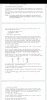
Theres bourn trim pots for all of them but unfortunately the pcb is not labeled at all and im just going by the schematic maybe you guys could confirm the test points with me so i can start checking if it needs adjustments.

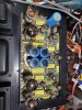
This is the overall look of the amp
20200304_161823.jpg

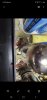
The manual says theres 1ohm wirewound resistors which you measure the bias across and they are supposed to in the cathode circuit of each output tube which im thinking are these ive circled in red int the following picture although they look to be carbon not like the wirewounds i typically see
Screenshot_20200304-162026_Gallery.jpg
 
have you checked power on both channels. One of the tubes (top one in photo) looks very used, but it doesn't mean it is bad enough to make only 2 watts.
 
have you checked power on both channels. One of the tubes (top one in photo) looks very used, but it doesn't mean it is bad enough to make only 2 watts.

Yeah i did both channels one is coming around 4 volts ac and the other 3.5v ac before clipping on the fluke
 
Yeah i did both channels one is coming around 4 volts ac and the other 3.5v ac before clipping on the fluke

Something is definitely wrong then, this is not normal. Begin by verifying that your meter is accurate at 1kHz, then check the bias, test the tubes, make sure the right tubes are in the right sockets, make sure the voltages are okay in the amp, etc etc.

You are measuring between 0 or C, and 8 ohms, right?

I just noticed that the schematic says that the 4 ohm tap is grounded on this amp, because of how the negative feedback is connected. If you are grounding the 0 ohm output to your scope, and this is in turn grounded to the signal input, then this could be the reason for the low reading. Try and measure voltage with nothing connected except your fluke and the dummy load, and just see how much voltage it makes that way.,
 
Something is definitely wrong then, this is not normal. Begin by verifying that your meter is accurate at 1kHz, then check the bias, test the tubes, make sure the right tubes are in the right sockets, make sure the voltages are okay in the amp, etc etc.

You are measuring between 0 or C, and 8 ohms, right?

I just noticed that the schematic says that the 4 ohm tap is grounded on this amp, because of how the negative feedback is connected. If you are grounding the 0 ohm output to your scope, and this is in turn grounded to the signal input, then this could be the reason for the low reading. Try and measure voltage with nothing connected except your fluke and the dummy load, and just see how much voltage it makes that way.,


That last part is interesting i had read about it but i thought since it mentioned the 4 ohm tap and i was on the 8 ohm then it didnt pertain to what i was doing.

So currently this the way i am taking the measurements i have the 8 ohm dummy load connected to the 8ohm tap on the amp on which i have the oscope probe connected to the assigned positive side of the dummy load then the ground from the probe is connected to the negative side assigned of the dummy load. I have a 1 khz sine coming from my kenwood signal generator which i verify before i use ever time with my frequency counter and i have the going into one of the rca jacks on the back of the amp then im using the amplitude knob on my signal generator to drive it to clipping the scope is a tektronix 465.

Ok now with that out of the way could you elaborate step by step the procedure you would like me to do now thanks again for all your help!!!
 
Something is definitely wrong then, this is not normal. Begin by verifying that your meter is accurate at 1kHz, then check the bias, test the tubes, make sure the right tubes are in the right sockets, make sure the voltages are okay in the amp, etc etc.

You are measuring between 0 or C, and 8 ohms, right?

I just noticed that the schematic says that the 4 ohm tap is grounded on this amp, because of how the negative feedback is connected. If you are grounding the 0 ohm output to your scope, and this is in turn grounded to the signal input, then this could be the reason for the low reading. Try and measure voltage with nothing connected except your fluke and the dummy load, and just see how much voltage it makes that way.,

If what you are saying is to leave everything the same but remove the scope from the equation how am i going to determine when it clips?
 
If what you are saying is to leave everything the same but remove the scope from the equation how am i going to determine when it clips?

Connecting the 0 ohm tap to ground, is the same thing as short circuiting the output of the amplifier. Are you familiar with how a bridge tied load (BTL) solid state amp works? This is a similar situation, where neither the 0 nor C outputs are grounded. If you want to see how it clips, connect the scope between "4" and "8", with "4" grounded and "8" to the scope probe input.. Do this, but connect the dummy load between "0" and "8", and the volt meter as well.

Make sense?
 
Connecting the 0 ohm tap to ground, is the same thing as short circuiting the output of the amplifier. Are you familiar with how a bridge tied load (BTL) solid state amp works? This is a similar situation, where neither the 0 nor C outputs are grounded. If you want to see how it clips, connect the scope between "4" and "8", with "4" grounded and "8" to the scope probe input.. Do this, but connect the dummy load between "0" and "8", and the volt meter as well.

Make sense?


No i am not familiar with that type of solid state thanks for the info its very informative. Ok

So essentially i leave everything as i have it connected except move the scopes ground to the 4 ohm tap is that correct?
 

THAT WAS IT!!! its measuring at 40 watts per channel before clipping wow the symmetrical clipping is spot on in this one thank you all for the help learned something new today!! Now if i might ask one more thing from you guys could you tell me if that resistor i sent is the correct one to measure clipping accross?
 
THAT WAS IT!!! its measuring at 40 watts per channel before clipping wow the symmetrical clipping is spot on in this one thank you all for the help learned something new today!! Now if i might ask one more thing from you guys could you tell me if that resistor i sent is the correct one to measure clipping accross?

What resistor?
 
What resistor?


According to the manual theres a 1 ohm wirewound resister that is connected to the output tubes where you measure bias accross it to bias the amp i included a picture at the top and circled them in red the ones i suspect they are unfortunately theres no markings on the amp
 
According to the manual theres a 1 ohm wirewound resister that is connected to the output tubes where you measure bias accross it to bias the amp i included a picture at the top and circled them in red the ones i suspect they are unfortunately theres no markings on the amp

To measure bias? You said clipping, this makes more sense now! The bias measurement resistors go from the cathodes of the output tubes to ground. You will have to find them on the board, I can't tell from the photo. You can find the pinout of a 6L6GC online. Make sure they actually are 1 ohm before adjusting anything, someone could have used another value which will throw your readings off.
 
Back
Top Bottom