• The move to the new server is done. There are some software and database maintenance updates in process. This has us passing the hat around to help out. We appreciate any donations. Seriously, even a dollar helps. The payment page may be found here - https://www.audiokarma.org/support.html

help with Carver M1.0t - powers on but no sound

Bobby DIG8L

New Member
I'm a bit of a newb but I'm into tinkering with electronics so I'm trying to figure this out. I got this amp used, it powers on but there is no sound output. I ordered a capacitor kit and installed the twenty-something caps that were in there, obviously no big power caps included but those seem fine anyway. It still has the same problem powers on but no sound, and now also the "headroom exhausted" light is on for one channel only, no other lights are on (except the very bottom one on both channels that shows power on).

Upon checking all the new capacitors against chassis ground I can see 2 of them seem to be grounding the side of the capacitor without the negative stripe (although the stripe aligns with the marking on the motherboard that should indicate the negative side). Should I ignore the markings on the board and flip those 2 caps around? There is also a cap that doesn't have either leg connected to chassis ground, could this be normal or is something connected wrong here?

I checked out the Carver troubleshooting guide but that keeps talking about a no power issue, which is not my problem so I don't think any of it is relevant to me? Please advise if I'm wrong in assuming this. Any help is truly appreciated.
 
Register to hide this ad
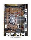
To clarify by an example: one of the capacitors in question is C501 in the attached picture which came in the guide that the seller sent me with the cap kit (I'll post that whole guide if I get a chance but it's mostly basic instructions and a list of the caps). This cap C501 is in area D4 in the picture and is indeed installed the same way as the picture (with the stripe to the right towards the edge of the board) but is reading as in-continuity with a screw on the frame at the other side of the capacitor without the stripe.

Also it's hard to see in the picture but the printed white square on the board I can confirm is on the side with the stripe, the same as it is on every other capacitor, but is reading backwards on the meter at C501 with the stripe not having continuity with the frame but the other side of C501 does.
 

Attachments

  • Instructions for M_1_0T Electrolytic Cap Replacement.jpg
    Instructions for M_1_0T Electrolytic Cap Replacement.jpg
    132.4 KB · Views: 8
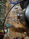
Looks like I may have damaged ZD101 as pictured when I test it on ohms it just keeps going up though to be honest I'm not sure how to test these. Also the resistor above it R309 is doing the same behaviour so I will replace it and probably this ZD101, everything else in the area seems to be reading something normal-ish enough. I think I knocked some of these out trying to get C306 out but I put them back so if I replace these 2 I think I'm clear.


30128897-E200-4599-8FC7-2F7E96E7329F_4_5005_c.jpeg

Some more readings while powered on, at TP5 I get about +30 to + 32 VDC to the chassis, at TP6 I get -30VDC. If combined I can get about +60VDC but nowhere do I see +100VDC as described in the troubleshooting manual maybe finding that would be a start. I get about +88VAC to those same test points to the power switch post. Adjusting the SVR301 doesn't seem to do anything or neither any other SVR but I think those are for adjusting the difference while powered off according the manual which I will post once I find somewhere to host it.
 
Last edited:
I feel like a crazy person talking to myself here but anyway I pulled the zener and the resistor above it to test. Zener is 13V one way and 0.7V the other way so I think it's fine but I might just replace it anyway. The resistor is reading 100K so it's fine too I think. Still wondering why I can't see +100VDC anywhere, and some input on the "backwards" capacitors would be great.
 
Back
Top Bottom