• The move to the new server is done. There are some software and database maintenance updates in process. This has us passing the hat around to help out. We appreciate any donations. Seriously, even a dollar helps. The payment page may be found here - https://www.audiokarma.org/support.html

Help with crazy modded ST-70 reversal. Again…

rudedogg

AK Member
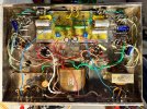
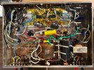
Hey everyone. I am working on this ST-70 that had some seriously messy and (to me) non-sensical modifications done previously. I have determined the driver board is a very early VTA70 variant. Using 3 12au7. I cleaned up the wiring as best i can for the moment. And i “think” i have the board and other connections correct. So i put it on a variac and limiter and ran it up to 75vac in. It played sound equally both channels. Did nothing bad. Voltages seem to be coming up OK. But at the bias sockets up front, i am seeing 4vdc already! No redplating yet, at least at the lower B+. I do not know the function of the 220uf electrolytic caps across the bias resistors. I left them for the moment. Could that be causing the high voltage?? Please anybody with more knowledge look at the amp and offer any input and correction if you can
Thanks!
Pics are before, and cleanup so far
 

Attachments

  • IMG_2841.jpeg
    IMG_2841.jpeg
    379 KB · Views: 76
  • IMG_2965.jpeg
    IMG_2965.jpeg
    403.1 KB · Views: 75
Register to hide this ad
Check the grid voltage at the output tubes, and verify the cathode resistors are actually a sensible value. Stock is 15.6 ohms, but 10 ohms or some other small value makes sense, it just alters what the correct value to measure is. High voltage across the resistor could be missing grid supply or just high value K resistors.

If you mean those big blue axial caps, I'm guessing someone had the idea to bypass the cathode resistors for some reason. Technically it would bump gain a smidge but its not really needed. Dynaco left them un-bypassed to introduce a wee bit of local feedback to reduce distortion in the output stage. They can stay or go but with 15.6 ohms its a pretty small change.
 
Check the grid voltage at the output tubes, and verify the cathode resistors are actually a sensible value. Stock is 15.6 ohms, but 10 ohms or some other small value makes sense, it just alters what the correct value to measure is. High voltage across the resistor could be missing grid supply or just high value K resistors.

If you mean those big blue axial caps, I'm guessing someone had the idea to bypass the cathode resistors for some reason. Technically it would bump gain a smidge but its not really needed. Dynaco left them un-bypassed to introduce a wee bit of local feedback to reduce distortion in the output stage. They can stay or go but with 15.6 ohms its a pretty small change.
Soooo i did not closely look at the cathode resistors. I “thought” they were 6.25 ohm replacements due to the added four corner idle trim. However, they are 625ohm… why would that be done i wonder?
 
Last edited:
Soooo i did not closely look at the cathode resistors. I “thought” they were 6.25 ohm replacements due to the added four corner idle trim. However, they are 625ohm… why would that be done i wonder?
Did they make it cathode biased? Like are the grids grounded with a 250-500K resistor?
 
yeah cathode bias, and thats an excessively large value. The Mullard 5-20 used a 470 ohm cathode resistor per tube.

I would get rid of all of that, if you don't have a 15.6 ohm sub in 10 ohm parts. Restore the bias supply so it has sane negative voltage and see what you get. Bias would be 1.0 volt with a 10 ohm per-pair cathode resistor, or 0.5 volts with a per-tube resistor.
 
Did they make it cathode biased? Like are the grids grounded with a 250-500K resistor?
That is exactly what appears was done. So what is the advantages of that mod? My instinct is to go back to fixed. This amp ate fuses and rectifiers according to it’s owner. So there was certainly a problem with current draw.
 
yeah cathode bias, and thats an excessively large value. The Mullard 5-20 used a 470 ohm cathode resistor per tube.

I would get rid of all of that, if you don't have a 15.6 ohm sub in 10 ohm parts. Restore the bias supply so it has sane negative voltage and see what you get. Bias would be 1.0 volt with a 10 ohm per-pair cathode resistor, or 0.5 volts with a per-tube resistor.
Yup! And thankyou. I reconnected the bias tap. I will get rid of those 625ohm resistors tomorrow and see what shakes out
 
The big advantage of cathode bias is reduced output power and higher distortion, at the expense of having to stick a meter in the test points and turn a screw to make it read a voltage. Because who wants good performance if it requires 30 seconds with a voltmeter every once in a while?

to be fair the rectifier will probably like it since the idle current with overly large resistors will be low and they also limit peak current at max output. The output tubes will also last a long time being under-biased.
 
An update to this project: i have “undone” the cathode bias scheme and reinstalled the fixed. I removed about 4 feet of super messy wiring and redundant components. And some i had no understanding of. All voltages are within spec currently also! A couple small issues yet to try and solve. 1) i can feel a vibration in the chassis while on. I cannot hear any mechanical noises from the chassis or PT. Also there is a small 120hz buzz at idle from the speakers.. I am hopeful this is due to some still quite sloppy weaving of filament, B+, and signal wiring. But it is a good sounding amp now. I am curious about the very early VTA driver board. This is running the trio of 12au7. Does anybody know what voltages i should see (other than filament) at pinouts?
 
One of my friends on another forum is really into the ST-70. For years he fought a problem regarding sound quality with the aftermarket boards. Couldn't put his finger on it, the sound just wasn't really up to par with other amps. He finally replaced the 12AU7 gain stage with 6CG7, and later I believe with 6SN7, both of which produced the beautiful sound he was looking for. I know people say that the use of the 12AU7 inside a feedback loop compensates for its non-linearities, but that doesn't seem to be the case for the ST-70. I attribute this to the fact that much of the necessary feedback is created with the UL taps, and less is applied in the loop that includes the gain stage. Maybe it's something else, perhaps the overall harmonic signature. In any event, you would be well advised to eliminate the 12AU7 for any use other than a cathodyne or LTP phase splitter.

Jack
 
Also consider with a 12au7 front end, the open loop gain is likely to be a fair bit lower than stock, which means less global feedback can be applied to compensate for the non linear nature. Stock st70 is like 20dB not including whatever happens in the UL taps
 
Unfortunately the driver board must stay. This was a clean up for a local member here. The amp was a really huge mess inside. I am doing this mostly as a favor, not a lot of parts cost. More removing piles of added useless mods and messy wiring than anything else. Should there be any concern over the tactile slight vibration felt in the chassis? This has the much larger aftermarket power transformer. And i tested the aftermarket can cap at 500v and it passed leakage testing. So not sure what that is???
 
maybe play with the bolt tension, or add rubber washers between the transformer and chassis if that does nothing. I wouldn't get too concerned about it though.

120hz could be poor idle current matching in the output tubes if its not individually adjustable.
 
maybe play with the bolt tension, or add rubber washers between the transformer and chassis if that does nothing. I wouldn't get too concerned about it though.

120hz could be poor idle current matching in the output tubes if its not individually adjustable.
I will see if adjust traffo fastening helps. The amp is converted back to “4 corner” idle. I used a 15ohm 1% resistor per power tube. So I set all at just under .75 volts. They all seem the same. Actual bias voltage is -32vdc per tube
 
An update to this project: i have “undone” the cathode bias scheme and reinstalled the fixed. I removed about 4 feet of super messy wiring and redundant components. And some i had no understanding of. All voltages are within spec currently also! A couple small issues yet to try and solve. 1) i can feel a vibration in the chassis while on. I cannot hear any mechanical noises from the chassis or PT. Also there is a small 120hz buzz at idle from the speakers.. I am hopeful this is due to some still quite sloppy weaving of filament, B+, and signal wiring. But it is a good sounding amp now. I am curious about the very early VTA driver board. This is running the trio of 12au7. Does anybody know what voltages i should see (other than filament) at pinouts?
the current board runs 3x12AU7. theres an alternate that uses 3x 6SN7. the old one ran 12AT7. other than that i dont know much.

the dynaco forum has a lot
of basic info about the vta kits and mods it may have that front and center.

fantastic work
 
Should there be any concern over the tactile slight vibration felt in the chassis? This has the much larger aftermarket power transformer.
I would short the inputs and measure noise output with a scope or sensitive RMS meter. Maybe it's not creating a serious issue.

Jack
 
the current board runs 3x12AU7. theres an alternate that uses 3x 6SN7. the old one ran 12AT7. other than that i dont know much.

the dynaco forum has a lot
of basic info about the vta kits and mods it may have that front and center.

fantastic work
An even better alternative is to install a clone of the original PC3 that uses 6U8 , reverting to factory configuration. Sound will be better and spec improves, NFB goes up from 9 to 20dB
It does include the reinstall of bias pots and bias components.
 
Hey guys. Another quick question: I added the “Yellow Paper” mod. This amp did eat rectifiers, most likely due to the excessive added capacitance in the PS, and modern tubes. Will this help with using modern manufacture rectifiers over old Mullard or Amperex parts? I know there has been much discussion on this mod and other options. Thoughts with just the original yellow paper idea?
 
An even better alternative is to install a clone of the original PC3 that uses 6U8 , reverting to factory configuration. Sound will be better and spec improves, NFB goes up from 9 to 20dB
It does include the reinstall of bias pots and bias components.
Honestly my favorite version of the ST-70 is my Will Vincent example. It uses high very quality components, a custom paint job and chassis work. But stays mostly true to the original circuit design. It runs 7199, comes with adapters for 6u8 I believe? And of the 6 ST-70s I have owned, bests all the others with all their crazy mods.
 
Hey guys. Another quick question: I added the “Yellow Paper” mod. This amp did eat rectifiers, most likely due to the excessive added capacitance in the PS, and modern tubes. Will this help with using modern manufacture rectifiers over old Mullard or Amperex parts? I know there has been much discussion on this mod and other options. Thoughts with just the original yellow paper idea?
The only thing that does is help with peak inverse voltage (PIV) failures. It won't help with things failing from excessive current draw. People say it makes the rectifier last longer but I've never owned one so I can't say for sure. Personally I'm unwilling to spend $100+ for a rectifier tube so if I did have one that fried a rectifier, it would end up converted to solid state to fix the problem forever.
 
Back
Top Bottom