


engstrom
New Member
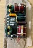
I'm a complete novice to the audio world and I'm hoping someone more experienced can help me understand the design of this crossover. It's from an Allen Organ HC-15 3-way speaker (15" woofer, 4" mid-range, & 1" tweeter).
I looked up a few 3-way crossover designs and the closest matches were 2nd order 3-way crossovers with reverse polarity mid-range. And as far as the tweeter and mid-range go, the diagrams I found online seem to line up perfectly with the crossover I have.
However, the low end of things has a few more components than the diagrams I found online. The designs I found all just have a single capacitor and inductor on the low end woofer but the crossover I have also has a couple more capacitors, a second inductor, and a 12-ohm power resistor.
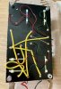
I took a stab at drawing a diagram of my crossover. Again, I have no idea what I'm doing so apologies for the mistakes I'm sure it contains. If you can help me understand the purpose of these additional components and what that means in terms of the type of crossover design this is, I would greatly appreciate it. Thanks!

I looked up a few 3-way crossover designs and the closest matches were 2nd order 3-way crossovers with reverse polarity mid-range. And as far as the tweeter and mid-range go, the diagrams I found online seem to line up perfectly with the crossover I have.
However, the low end of things has a few more components than the diagrams I found online. The designs I found all just have a single capacitor and inductor on the low end woofer but the crossover I have also has a couple more capacitors, a second inductor, and a 12-ohm power resistor.
I took a stab at drawing a diagram of my crossover. Again, I have no idea what I'm doing so apologies for the mistakes I'm sure it contains. If you can help me understand the purpose of these additional components and what that means in terms of the type of crossover design this is, I would greatly appreciate it. Thanks!


