• The move to the new server is done. There are some software and database maintenance updates in process. This has us passing the hat around to help out. We appreciate any donations. Seriously, even a dollar helps. The payment page may be found here - https://www.audiokarma.org/support.html

Help with SA-6500 II

clk1981

Member
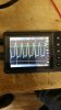
I'm hoping someone can help me figure out this problem I am having with a Pioneer SA-6500 II. The unit powers on, and I get a perfect sine wave out of the outputs at LOW volume (Volume knob is 0-10). When the knob gets to around 3, I notice distortion and the bottom half of the sine wave clips on BOTH channels.

Under no load (no speakers, no dummy load) with scope hooked up to speaker outputs, the sine wave does NOT clip at any volume level whatsoever.

I have recapped the entire unit, except for the two main filter caps which show good on my ESR meter. I have also replaced a few transistors that had corroded legs and nothing has changed anything.

I still get distortion/clipping as the volume increases when speakers are attached.

any help would be greatly appreciated.

Attached is picture of my scope.

Thank you!
 

Attachments
  • 20171214_092129.jpg
    20171214_092129.jpg
    38.6 KB · Views: 24
Last edited:
Register to hide this ad
If it is doing it on both channels then it is a common problem to both, it is PS issue or you changed something during your fix up. Depending on the condition, I always recommend to do one channel at a time so you if one channel is still working, you have the other to compare against.
Check all the DC power supply voltages against the schematic, esp when the clipping.
Post where you see differences.
Determine what gain stage where it is clipping, is it clipping in the preamp or in the power amp?
 
It was doing this before re-capping. I re-capped and it didn't fix it. I'll check some voltages and see. There isn't a preamp output either but coming out of the tone control sections I believe it was fine.
 
Sorry I can't be much help here but I can tell you that I have seen 3 others (SX-6500ii) over the years doing the same thing. I was never able to come up with a total solution. I made the last one I saw much better by substituting all 17 transistors in the amp stage with modern equivalents but with only marginal results (maybe 5.5 on the volume dial). I never found a true solution and I am looking forward to seeing what you do to yours. Interestingly, never had this problem with the original 6500.
 
the drivers will actually move enuf current to play a small set of speakers a little and headphones. installing the amp up to and including the drivers, but not the outputs is a good way to make sure everything else is in place and working, once you do verify, you weld in the outputs, emitter resisters and set some voltage etc, if the outputs are not working, but everything else is, what you describe could happen. the 2sa850/2sc1735 set are the drivers
 
the drivers will actually move enuf current to play a small set of speakers a little and headphones. installing the amp up to and including the drivers, but not the outputs is a good way to make sure everything else is in place and working, once you do verify, you weld in the outputs, emitter resisters and set some voltage etc, if the outputs are not working, but everything else is, what you describe could happen. the 2sa850/2sc1735 set are the drivers

The drivers have operating voltage, and pass a diode check, and I checked all of the resistors around them and everything seems fine.

I did notice though that the outputs have 36V / -36V and the service manual says it should be 31V / -31V. Every transistor seemed to have slightly higher voltage readings than what the service manual says.
 
but whats the gain like the other poster said? if you feed it a 1khz signal at 200mv, whats the output voltage?
 
but whats the gain like the other poster said? if you feed it a 1khz signal at 200mv, whats the output voltage?

Sorry, I am fairly new to this so I don't know if I have the right equipment. When I was generating sine waves before I was using the headphone jack of an older cell phone using an app to generate frequencies. Also, are you talking feeding the input via the aux or tape inputs or directly into the transistor? I have a cheap-o chinesium transistor tester that I believe tells me the gain. Would it be best to pull a few and use that?
 
you can pull and test and if they test well, it just meanthing else in the output circuit is kerflooey.

I have a function generator, but you can get them cheap off amazon, somethign that will put out 1Khz from 2-500mv will be adequate for most amps.

and you read the result via whatever scope you have, I have an old CRT BK and I just got pc oscilloscope to use so either will work
 
Was that amplifier worked on BEFORE you ?
Original output transistor ?
Crazy thing that only the bottom half would clip !
Only one transistor on both channel would be sick . As I understand AB class amps, one power transistor
is there to do the job on half the audiowave.
Check for original power transistor.

I'm not an expert.
Good luck !
 
Was that amplifier worked on BEFORE you ?
Original output transistor ?
Crazy thing that only the bottom half would clip !
Only one transistor on both channel would be sick . As I understand AB class amps, one power transistor
is there to do the job on half the audiowave.
Check for original power transistor.

I'm not an expert.
Good luck !

Everything does indeed look original. Since the bottom half is the only one clipping should I be looking at the NPN outputs?
 
Do you have the service manual ?

Go to Electrotanya and type in pioneer SA-6500-2 ( not II )
 
ok, I have the service manual and I am writing down all the locations and transistor numbers to take over to my bench. I will trace the signal. It looks like Q2 and Q3 are the tone amplifier that then sends signal to Q4 entering the power amp stage. I am having a hard time finding Q2 at the moment though.
 
Back
Top Bottom