
• The move to the new server is done. There are some software and database maintenance updates in process. This has us passing the hat around to help out. We appreciate any donations. Seriously, even a dollar helps. The payment page may be found here - https://www.audiokarma.org/support.html

Help with sizing safety caps?

GlasgowGrip

Sound just like a record on the phonograph
Subscriber
Hello All,
I wanted to run something by everybody as a sanity check and to ask a nagging question. I'm at the tail end of upgrading a Hafler DH-101 preamp (I refurbished the power supply and main boards, replaced the RCA jacks, modified some of the grounding scheme, and deoxidized/lubed the pots/switches.)

The last thing on my list is to replace the sketchy power cord, so I have a new polarized two-prong cord ready to install. I will be wiring the smooth (Hot) side of the cord to the power switch, and the ribbed (Neutral) side to the bus that connects to the fuse on the power supply board.

But... while I'm at it I want to replace the 45-year old across-the-line cap C23 and the two line-to-ground caps C22/C28 with modern X1/Y2 safety caps. (I assume these are there for EMI/RFI suppression.)

So here's my question: the Hafler manual called for 0.01uF/1kv ceramic discs, but the unit as built has 0.005uF/1kv ceramics installed. How important is the difference? And which value should I go with?

My two candidates are Kemet X1 400VAC/Y2 250VAC ceramic safety caps, I bought both 0.01uF and 0.0047uF. I'm leaning toward using the 0.0047uF's for the two line to grounds, and the 0.01uF for the across the line, but I don't really understand the logic behind how to size these. Any thoughts on which is better?

Thanks in advance! - Steve
 
Last edited:
Register to hide this ad
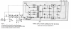
Here's a schematic of the situation, I marked it up with the safety cap values I plan to use:
DH-101 SafetyCaps.PNG

Any comments on this plan?

Besides the safety cap sizing question, this also nags at me: since there is no true earth ground in play, what is the primary function of the two line to chassis ground caps? In one sense they function like an additional across the line cap, don't they? And I see how they keep the potential of the chassis centered (more or less) between the positive and negative peaks of the AC mains voltage, yes? So the chassis potential floats right around ~60VAC measured to earth ground (assuming Neutral is bonded to earth back at the breaker panel). Without going to a three-wire line cord, would it make more sense to reference the chassis ground to Neutral through a large value resistor?
 
The value isn't overly critical. Z of a 0.005uf cap at 60hz is 53K, 0.01uf is 26.5k. Max current flow at 120vac is 2.2ma or 4.5ma respectively. So long as they are the same value you'll get chassis potential at ~1/2 mains voltage. as to whats better I don't know. I suspect it doesn't make a huge lot of difference but when in doubt I go with whats in the unit vs whats on the schematic. The smaller value cap does end up with less wasted power. Wired like they are, it would be like 106k, or 1.1ma of waste current flow through the two caps.


If you have a polarized cord on it, you could just eliminate the cap on the hot side to chassis. At that point the chassis would be at ground potential via the cap, provided your outlets are wired correctly.
 
@gadget73: I have already installed the polarized line cord as shown, so I will strongly consider omitting the cap from Hot to chassis. I like the idea of the chassis being essentially at ground potential. Of course I will test first to see if this introduces any issues with hum, though it doesn't seem like it should.

And thanks for the pointer on looking at the caps' Z @ 60hz, I knew I wasn't thinking about it correctly.
 
@gadget73: I have already installed the polarized line cord as shown, so I will strongly consider omitting the cap from Hot to chassis. I like the idea of the chassis being essentially at ground potential. Of course I will test first to see if this introduces any issues with hum, though it doesn't seem like it should.

And thanks for the pointer on looking at the caps' Z @ 60hz, I knew I wasn't thinking about it correctly.
Keep in mind something about house wiring. The Neutral is always "hot" when in circuit because the ground is further downstream and conducts all the way until that point. That also means anything else on that receptacle circuit when turned on makes the Neutral "hot", even in your unswitched outlets. Safety caps will be needed on both Hot and Neutral. One across the line H/N, one Neutral to chassis ground, and one Hot to chassis ground. The ones going to chassis should be fail short safety caps (they will trip your receptacle breaker if an unsafe condition develops). The L/H safety cap needs to be a fail open safety cap. If it fails, all that happens is it stops filtering the "buzz", and indicates there was a spike in AC line voltage above it's rating.. Using X2/Y2 rated safety caps will be adequate for all 3 caps since they cover both X and Y for safety in one package.
 
Indeed. Because the "Neutral" wire (technically the grounded conductor) is a current-carrying wire in this case, it is subject to voltage drop when the circuit is loaded.

The amount of voltage "hot" above ground depends on length of wire/measurement distance, wire gauge, current/load, and even temperature.

For example, on a circuit of 50 ft of 14ga wire with load of 5A, one might expect to see roughly 0.8 Volts to ground at the load end of the Neutral wire. Increase the load to 15A and the voltage goes up to about 2.4V (but then is above 3% allowed by NEC for branch circuits).

Consider the same on a 12ga circuit and the voltages are roughly 0.5V and 1.5V respectively.

If the circuits and loading are within NEC, one would not expect to see more than about 1.8V max to ground at the load end of the Neutral wire of a 120V circuit.
 
Last edited:
Understood, I am keeping both the H and N line-to-chassis caps. I have followed the marked-up schematic as shown above in post #2, using Kemet C900-series X1/Y2 rated ceramic safety caps at positions C22, C23 and C28.

Many thanks to everyone for sharing your knowledge!
 
Back
Top Bottom