• The move to the new server is done. There are some software and database maintenance updates in process. This has us passing the hat around to help out. We appreciate any donations. Seriously, even a dollar helps. The payment page may be found here - https://www.audiokarma.org/support.html

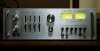
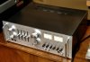
HH Scott A-436 Restoration

Knowns:
Amp doesn't have a speaker protection circuit. I haven't cleaned the power switch yet.

Issue:
Immediate "pop" through the speakers when turning power on. Nothing too alarming, but I'd like to take care of it too.

Quick question: Is it likely to go away with a cleaning, or should I be looking more at the cap that's associated with the switch?
 
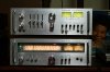
Scavenged some parts from the T-526 Tuner (restoration here) to complete this. New rack handles are just Liberty 96mm Satin Chrome drawer pulls, though I had to widen the holes a little each end (might have been 94mm on center). Still deciding whether to attempt some black paint lettering and/or at least the lines around the EQ. Looks like the tuner may be beyond repair...no sound, though good volts off the PS. I think the PLL chip may be bad, but still need to do some switch cleaning. Perhaps no signal is getting to it from the selector switch or elsewhere. So, here's another "not-so-Ugly Betty".

Anyone know if a phone based signal generator app will be strong enough for setting the power meters with a 1KHz sine wave?

eIMGP2301.JPG

eIMGP2302.JPG
 
Last edited:
So, I've been burning it in since the restore to shake out any issues, and one did crop up. Every now and then a spike would come through the speakers, but I wasn't really thinking much of it since I've been playing a lot of albums and most have a bit of snap crackle and pop. Today was mainly radio at first on the T-526, and there it came again. So having recently looked again at the bad transistors list,I decided to dig back in again to the PS and the Main amp board, as I'd left a lot of originals in there if they tested OK. Found several different things installed as compared to the scat/component list. Ended up replacing all but one remaining 2SC733 on the PS board. It also still has the original outputs. One of the transistors (a driver) had a leg snap off, and another looked really tired. So far, no spikes! And Abbey Road on vinyl just sounded amazing.

Things that got replaced today:

PS Board
4 x 3A 100V rectifiers (real crusty legs from some corrosion) -- IN5404 (3A, 400V)

Q901 - SM says 2SC733, that was installed and stayed since it measured 500+ hFe and I only have the KSA733 in the 120-240 range

Q902 - SM says MPS9484, found 2SA661O, replaced with KSA916Y

Main Amp Board
Q803/813 - SM says 2SA682 (or A777), installed was MPSA56, replaced with KSA916Y
Q806/816 - SM says 2SC1382 (or C1567), installed was MPSA06, replaced with KSC2316Y
Q805/815 - SM says 2SC372, installed was 2SC372, replaced with KSC1845P
Q808/818 - SM says 2SA495, installed was 2SA495, replaced with KSA992P
Q809/819 - SM says 2SA794 (or A682), installed was MPSA56, replaced with KSA916Y

Q804/814 - SM says MPS9630 (orC372), installed was 2SC372, replaced with KSC1845F

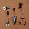
These are the thermal tracking bias Qs attached to the heat sink. Hopefully the 50mA rating won't be an issue here (C372 has 100mA). I didn't have correct pinout unless I went with something like the KSC2383. The Yamaha CA-800 used 2SC458 for the same purpose and those got replaced with the KSC1845, so...

After all that, I DBT'ed it, and reset the bias and DC Offset before hooking it back up. No pics though, forgot. It does seem to have more power/authority and cleaner presentation, so glad I went to the effort. Especially with that bad driver.

 
Last edited:
With so many different transistors than the SM, do you think they were factory subs or someone else’s past work?
 
It had been worked on in the past. Also, the SM was for 3 models... the 416, 426, and 436. A couple of the different Qs were listed for the lower powered versions, some for all three, so perhaps whoever worked on it was (won't name the service sticker and have no idea how many years ago it was worked on) just using what they had (kind of like what I did after a bit of research today). Also, two of the rectifiers had been replaced at some point...two had clear markings, two didn't have any marking except for leads colored red where there's usually a strip indicating polarity. As to the MPSA56 and 06 pairs, who knows?
 
Last edited:
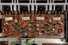
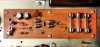
Final pics of the above work. I also replaced a couple of resistors with metal film on the amp board. Listening right now. Nice and clear.

A436 Amp Board Final.jpg

A436 PS Final.jpg
 
Argh..............Magic Smoke Escaped!

Got a nice price on some beef tenderloin today, so put on a CD and went upstairs to further trim and cut into steaks. Listening to the Cure when I smelled something that didn't seem right! :yikes:

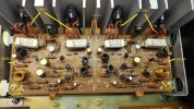
Ran downstairs and found only one speaker putting out sound, so shut things down, pulled plugs, etc. having read about speaker fires, etc. Pulled the amp out, opened the cover and was greeted by some major damage. :( Now to figure out what happened to cause it. Volume was up a little, as I was up in the kitchen, but I didn't think too loud. Bass boosted just a little, but loudness switch not engaged. Don't have knowledge of how to scope things to see if there was unwanted oscillation, so will have to do things the old fashioned way, with a DMM.
 
So, here's what I've found so far...

L Speaker fuse blew (3.5A)

Q804 (KSC1845) - Bias tracking on heatsink is bad but the 0.047uF ceramic cap across B-E is good
VR809 - Bias trimmer tests good as do the double diode and 1.2K R

Q803 (KSA916) and 806 (KSC2316) (center of board) are bad (but C805 tying the bases together is good)
Q808 (KSA992) is bad (chunk even blew off the body)
Q809 (KSA916) burned hot enough to lose a leg (base)
R813, 817, 818 all burned (818 almost through the board)
D802 (MA150) is open. Looks like 1N4148 should work fine here.
C811 (1uF/50V UPW) was in the middle of all that mess and still checks good (though will be replaced along with several of the other components that test ok)
Outputs test good :idea:

So, any guesses as to what led to this chain reaction? Bias Q804 (which I wondered about Ic) fails causing the outputs to somewhat runaway and draw more current than the other components could take? Only reason they're ok was the big heat sink and me smelling it and shutting it off? I do still have the 2SC372s that were the original bias Qs, so could put them back in and I could also use something else for Qs 805 and 808, or I could reinstall the C372 and A495s. Can't scope it to see if oscillation is/was a culprit. One thing I did notice in addition to the numerous transistor differences already mentioned, is that R818 (10ohm 1/2W) does not have the 0.002 cap in parallel with it like the scat calls for and that ties to the emitter of Q809.

If the Q subs I made leave something to be desired, suggestions as to more appropriate Qs are very much welcome. I will link datasheets back to post #24.
To strengthen the board where it's charred, I was thinking JB Weld or just a clear two-part epoxy. Any thoughts? Will have to do a little point to point on the trace side, but most traces are actually intact.

eIMGP2365.JPG

eIMGP2366.JPG

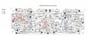
A436 Amp Layout Damage.jpg

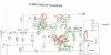
A436 Scat Damage.jpg
 
Cool you brought this back to life, looks real nice. Bummer about the blow up.

As a general rule don't use parts with Ic below original spec unless actually calculated to be OK. No reason to here, just use KSC1815 and KSA1015 which exceed specs of the originals (at quick glance, do check). I'd put those everywhere you used a 50mA part where spec was 100mA - which if I read correctly was not just the bias tracking transistors.
 
Unfortunately none on hand or I would have. And it looks like none of the places I regularly order from has the KSC1815.
 
Board repair

After reading a couple different sources I decided to go with epoxying a small piece of bread board to the component side after scraping away as much of the carbonized board material I could. This actually broke open a hole clear thru the board. I wanted to make sure the area under the replacement components was stable, so after the epoxy dried, I made sure the holes were drilled clear (no, they didn't really line up well with the layout of the board). Wanting to fill the gap left by the cut out of the carbon, I decided to fill it with JB Weld, as it can take the heat and is electrically non-conducting (though I'll verify that after it sets up). I remember it being used to form replacement STV diodes made from 1N4148 or others. To make sure the holes stayed open, I used short pieces of solder as "place holders" for the epoxy to flow around. Then I'll melt the solder to clear out the hole for the component legs. Here's the trace side.

JB Weld Board Trace.jpg
 
As I consider my options for replacing the 2SC372 and 2SA495s in a couple locations, I'm thinking that the KSC815/KSA539 pair might work better than the KSC1845/KSA992 combo. There's no problem on the main board with leg orientation due to the "triangle" nature of the holes. To use the 815 as the thermal tracker though, I'll have to insulate and cross the legs, as I don't have the center collector version. No chance at getting the KSC1815 currently, so need to go with what I have. I do have KSC2383 also, which could be used on the heatsinks, but not sure it's the best option to replace the C372s that were there. Thoughts? Only uploading the KSC815 as the KSA539 has same specs but is PNP to replace the A495.
 

Attachments

Q804 (KSC1845) - Bias tracking on heatsink (Replaced with KSC815) 0.047uF ceramic cap across B-E is good (reinstalled)
VR809 - Bias trimmer tests good as do the double diode and 1.2K R (reinstalled, though double diode changed with 1N4148 pair)
R822 - 3W 0.27ohm bias resistor checked good. (reinstalled)
R815 (tested good) R817 (burned). Both 330ohms (replaced with new Dale RN60 series)
Q803 (KSA916) and 806 (KSC2316) (center of board) are bad (replaced with same) (but C805 56pF is good) (reinstalled)
Q805 (KSC1845) is bad (replaced with KSC815)
Q808 (KSA992) is bad (chunk even blew off the body) (replaced with KSA539)
Q809 (KSA916) burned hot enough to lose a leg (base) (replaced with new KSA916)
R813, 817, 818 all burned (818 almost through the board) (replaced with new Dale RN60 series)
D802 (MA150) is open. (replaced with 1N4148)
C811 (1uF/50V UPW) was in the middle of all that mess and still checks good (replaced with 1uF/63V Kemet R82)
Outputs test good :idea:

On the Right channel I replaced Q814 (bias tracker) with KSC815, and Qs 815 and 818 with KSC815 and KSA539 respectively as on the L channel

Placed it on the DBT, which glowed then dimmed as it should and checked the Left Amp bias...29mV vs 8mV and couldn't adjust it. :yikes: No wonder components burned. Quickly shut it off. Checked the R channel briefly...5.6mV on the DBT

So, though the outputs pass the 6 way diode check out of circuit, are they suspect? Trimmer checked good also, as did the bias resistors. What's the likely culprit for high non-biasing outputs?

But here's a new piece of information...I hadn't checked the speakers (Avid 102s), though I did recap the crossovers with PP Daytons. The left speaker (at the terminals) measured 2.4 ohms! The right 6.7 ohms (8 ohm nominal). Pulled the tweeter for the Left...right around 8 ohms. Woofer 2.4 ohms. Pulled the right woofer...6.4 ohms. Now, this becomes a chicken and egg question...did the amp issue cause the woofer ohm drop, or was the 2.4 ohm load what caused the L channel to burn up? If the latter, why won't it bias with the new components installed, or does this again point to the outputs?

A436_Repair_Component_Populated.jpg A436_Repair_Trace_Populated.jpg
 
Last edited:
Bringing this back up.... And still looking for why it won't bias...trimmer has no effect (tested fine out of circuit and checked it vs the good R channel but haven't swapped them yet).

My order of KSC1815 and KSA1015s arrived and I finally had a chance to install them, so all C815s and C1845s (diff pair) have been changed to C1815, and the A539s changed to A1015s. Still no effect, but didn't really think different Qs than the C815/A539s I tried out. Just not sure why the trimmer has no effect. I installed new outputs even though all the originals passed the 6-way diode test. Any ideas about the trimmers or what's not turning on/off causing the trimmers to have no effect???
 
Finally solved it....found two small signal diodes were also taken out in the damage...D805 and D806...were acting like resistors. Replaced with 1N4148s and all is now well with the world!

EDIT: Lesson learned: when there's a known issue, don't assume parts are ok if they appear fine, just pull and test them all. Would have discovered it during the board rebuild and could have buttoned everything up months ago.

picture145453.jpg
 
Last edited:
I have a 437 with an amp board voltage issue and could use some guidance if possible.
started new thread here,


Attachments

  • 437 amp photo 1.0.jpg
    437 amp photo 1.0.jpg
    151 KB · Views: 15
  • A437 Amp PCB.pdf
    A437 Amp PCB.pdf
    193.9 KB · Views: 3
  • 437 amp photo 2.0.jpg
    437 amp photo 2.0.jpg
    146.8 KB · Views: 15
Last edited:
@jheu02 , loving this thread (realizing it's "older"), but curious if this restoration was ever completed. For case corrosion, I was going to recommend a product called "Lightning rust remover", which is an aqueous solution of phosphoric acid - from REAL PRODUCTS in NEY, OHIO. I have used this extensively in both pinball metal part restoration as well as car restoration. Brilliant stuff - expensive ($50/gallon) but lasts a LONG time and is the BEST soak for rusty parts.

I'm looking at a Scott A-436 locally, and wondering if it's worth my effort. Thanks!

-Chris
 
Back
Top Bottom